The dsl 1 was mounted below the instrument cluster. Cable dcp power and remote start cable.

Edc Iii Components Engines
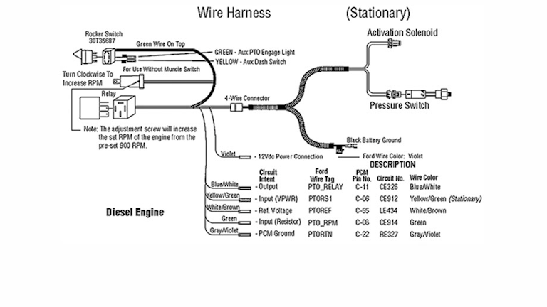
Rpm sensor wiring diagram. Tachometer signal or coil or tachometer sensor in order to measure engine speed rpm. Cable dcf flowmeter cable. Download your wiring diagrams here. If there is surface wave action then it may be advisable to use a stilling tube. Pressure sensor wiring diagram duration. Refer to the wiring diagrams figure 8 to figure 23 for proper wiring installation.
Wiring diagram for aftermarket tachometer a tachometer is gauge to measure mechanical speed in units of rpm revolutions per minute or rotations per minute. Most models also have black white only. This video is dedicated to cam and crk sensor testing and operational parameter but from an electrical and wiring diagram interpretation point of view. Plug the connectors back into the pressure monitor. Dual function cable srpm and digital. E1 0119 6 automation products roup inc.
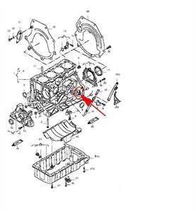
Carefully push the wires into the electrical box and mount the pressure monitor. The cam and crk sensors are types of speed. The linked images are printable but may print across more than 1 page in order to be legible. I also ran two wires from the gear tooth sensor to this location and finished wiring the dsl 1. The rpm device must be rotated by the display down then the correct wires according to the diagram on the back. Cable dca analog cable diagram.
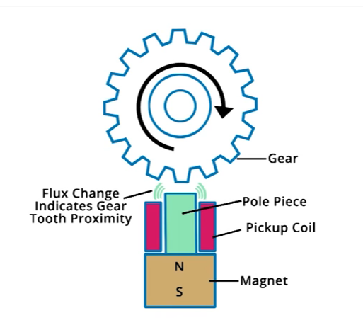
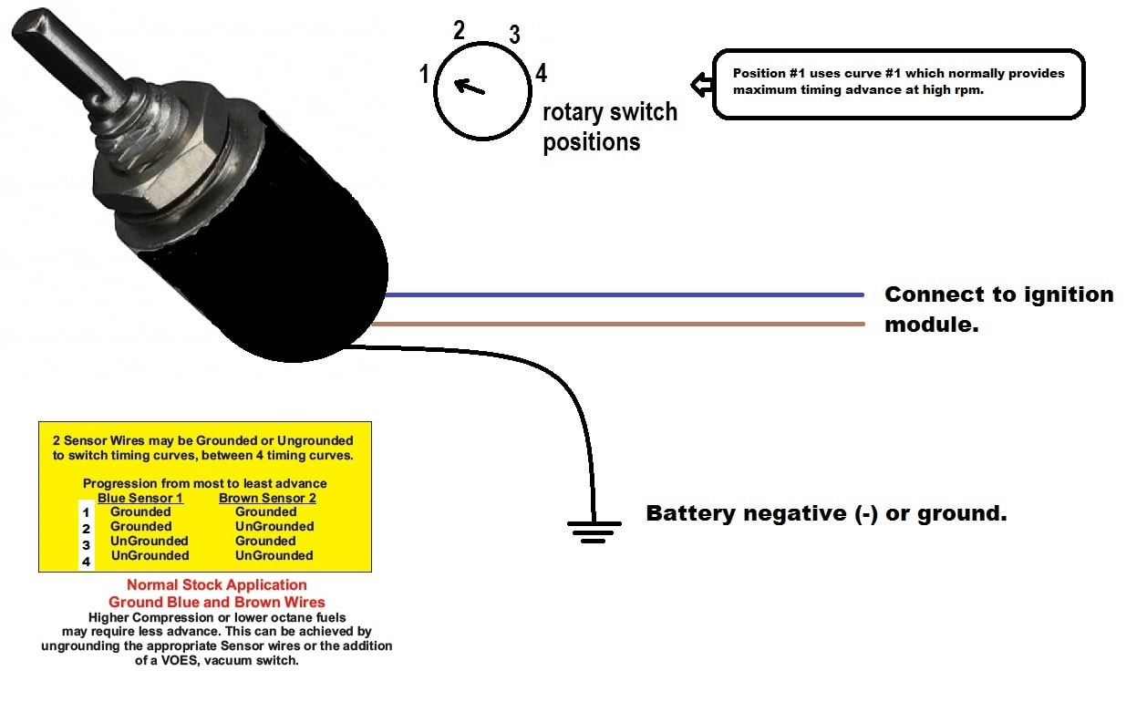
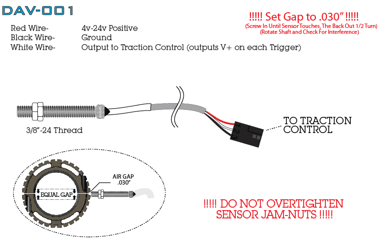
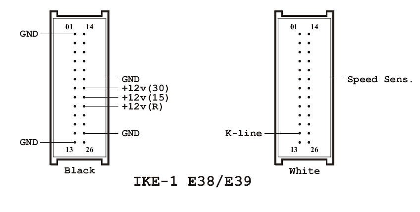
Inductive and hall effect rpm sensors explained. Here is a description of electrical wires on connector. Three wire sensor in plc three wire sensor connection in plc. Since he is testing the 2 wire speed sensor while it is out of the vehicle he breaks out the high powered drive device a drill to spin the sensor at the necessary rpms to generate a signal. Please see the table below the negative. The positive power pole is connected to the brown wire for the magnetic sensor negative power pole speed sensor blue wire from the sensor fourth position nothing connect.
Install four screws to. On vehicle tachometer is measuring engine speed. If you are intending on testing the vehicle you will actually have to drive the wheels with the engine to obtain sufficient rpms to generate a signal. Cable dcr rpm cable. If additional options need to be wired refer to building prints for proper wiring diagram. Cable dcrc custom rmp cable.
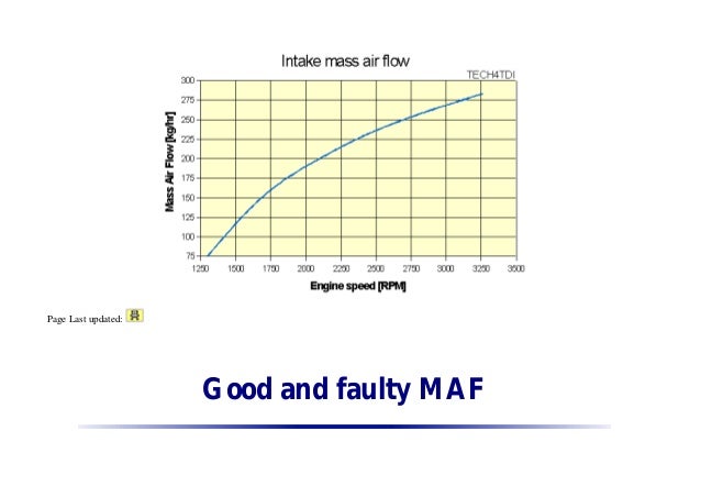
I pulled out my spreadsheet for rpms at speed in the different gears and saw that the engine should be turning 2000 rpm at 55 mph.
Gallery of Rpm Sensor Wiring Diagram