Protectors provided as per diagrams e f g. Bms1215s2 shunt and battery wiring.

Redarc Bcdc 1225d And Sbi12 Solenoid Install In Prado 150
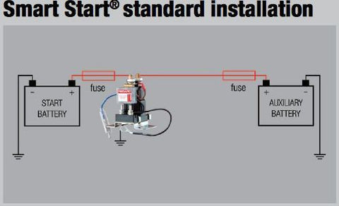
Redarc sbi wiring diagram. Redarc recommends connecting the sbi as close as possible to the start battery. Redarc recommend manual reset circuit breakers however fuses are acceptable. The redarc smart start sbi12 is a microprocessor controlled battery isolator which protects the start battery from excessive discharge while allowing the auxiliary battery to supply charge to non essential loads. Bcdc1240 with sbi under bonnet. The redarc smart start sbi is designed to be used in multi battery applications as a solenoid priority system to protect the start battery from excessive discharge while allowing the auxiliary. When using fuses make sure that the fuse makes a good low resistance connection.
Redarc electronics have a large database of faqs tech tips wiring diagrams and how to guides. See the guides below. It is used as a solenoid priority system in dual battery systems and provides 12v dc incorporating 100a of continuous ratings. 6 mount the sbi unit in a convenient location as shown in diagram k. Sbi sbi with external led sbi with push button for start assist momentary pushbutton. The redarc sbi wiring kit value pack comes with a redarc dual voltage gauge g52 vva and a smart start battery isolator wiring kit sbi12kit 55119 aud smart start battery isolator wiring kit 12v.
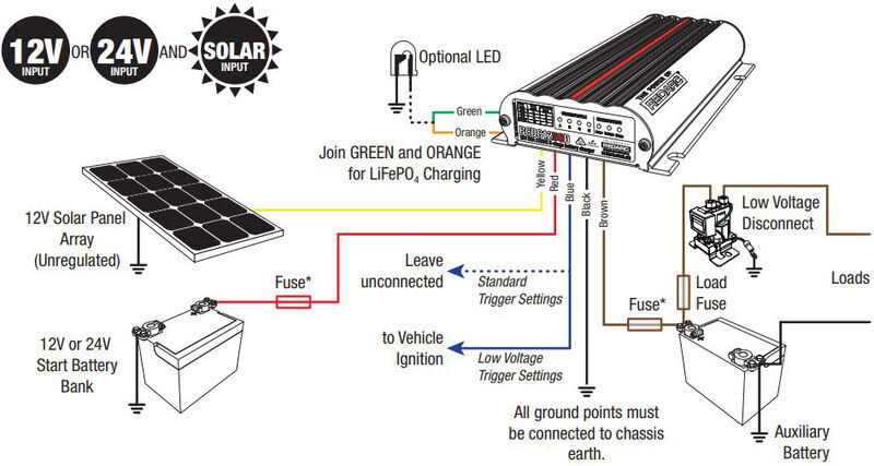
Bms1215s2 12v setup with amorphous blanket. Bcdc 3 way anderson setup. 7 connect the sbi ground wire to chassis earth as shown in diagram l. Redarc wiring guides for battery chargers and isolators. Check them out today. Learn to wire a bcdc1240 with sbi under bonnet.
When wiring a gauge into a location other than a car dashboard for example in a caravan park and dash lights may not be available. Redarc bcdc1240 and sbi under bonnet wiring guide. How to wire a redarc small battery isolator sbi learn to wire a basic sbi install with the below guide. Circuit breakerfuse ratings are dependent on the type of installation and the size of the loads. The below diagram shows how to install a gauge using switches to simulate ignition and dash lights providing a simple way to switch the gauge onoff both withwithout the backlight active.


