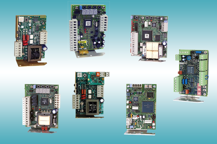
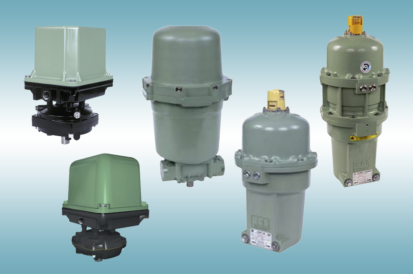
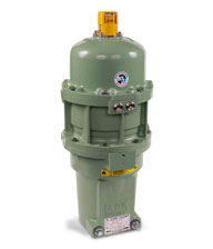
Mgo instructions 3 1 11 dayton schematics user manual and wiring diagram 31 rcs actuator wiring diagram list wiring diagram for actuator mgo instructions 3 1 11 dayton schematics user manual and wiring diagram 31 rcs actuator wiring diagram list wiring diagram for actuator adb limitorque l120 wiring schematic resources automated valve control 31 rcs actuator wiring diagram. Knob models mardcr10 50 90 only.
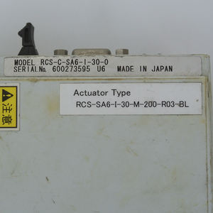
Rcs Actuator Rcs Actuator Suppliers And Manufacturers At
Rcs mar actuator wiring diagram. Flosource is an stocking distributor for rcs electric actuators. A wiring diagram is a streamlined standard pictorial representation of an electric circuit. These rotary models span a torque range of 120 to 48000 inch. Relays and controls are sold separately. Wiring diagram is drawn with the actuator in the open position. Rcs electric actuators can be found in the most challengining and demanding environments including.
14 turn and multi turn valves and dampers rcs electric rotary actuators are also well suited for use in the automation of other types of rotating equipment. Targeted to 14 turn and multi turn valves and dampers rcs electric rotary actuators are also well suited for use in the automation of other types of rotating equipment. Oil gas water wastewater power generation pulp paper steel processing aluminum processing chemical automotive and tunnel ventilation. Dresser rcs actuator mar 10 dresser rcs actuator mar 50 dresser rcs actuator mar 90. Wire per diagram or if actuator is of special design wiring diagram is included with unit. Mar wiring diagram for 120 vac actuators without internal relay notes.
Switch shown for illustration only. Rcs mardcr 10305090 rcs electric rotary line offers a broad range of highly versatile actuator products. 10051 porter road suite 900 la porte tx 77571 t. It reveals the elements of the circuit as simplified forms and also the power and also signal links in between the tools. Since 1966 rcs has been making electric quarter turn actuators in america. Use 18awg stranded wire or better for field hook up.
July 7 2018 by larry a. It reveals the elements of the circuit as streamlined shapes as well as the power as well as signal connections between the gadgets. Power to terminals 1 and 2 operates the unit into the open position. The percentage of time the electric motor is energized vs. Remove the hex bolts located around the enclosure of the actuator. Actuator is shown in open position.
Variety of rcs actuator wiring diagram. Power to terminals 1 and 3 operates the unit into the. A wiring diagram is a simplified traditional pictorial representation of an electric circuit. The time it is at rest in reversing duty and with the actuator running at its rated load maximum published torque. These rotary models span a torque range of 120 to 48000 inch pounds with stroke speeds for. Rcs actuator wiring diagram sample assortment of rcs actuator wiring diagram.


