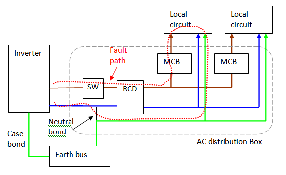
How to wire rcd distribution board. In the above distribution diagram i shown the wiring installation of double pole mcb circuit breaker rcd circuit breaker single pole mcb breakers voltmeter light indicator.

Zb 6391 Hpm Rcd Wiring Diagram
Rcd wiring diagram nz. Understanding your consumer unit layout identifying conductors spds mcbs and rcds fuse box duration. A wiring diagram is a simple visual representation of the physical connections and physical layout of an electrical system or circuit. Distribution board installation with rcd residual current device. Here is the rcd wiring diagram in which i install the main distribution board. Diy home electric supply with rcd wiring installation tutorial. In new zealand it is most common for the coloured wires inside power cords to look like either a or b.
If you look at the circuit diagram i posted in option 2 the neutral to each socket or sockets protected by a miniature circuit breaker comes from the rcd neutral bus not the main neutral bus which will be used for other supplies such as cooker air conditioning etc etc. The installation of rcd is too simple in single phase wiring main board. They should be connected as illustrated below. Residual current devices rcds are devices intended to isolate supply to protected circuits socket outlets or electrical equipment in the event of a current flow to earth that exceeds a. How to wire rcd residual current device. Wiring of the distribution board with rcd single phase from energy meter to the main distribution board fuse board connection electrical technology domestic switchboard wiring diagram nz this is how the connections to be done inside the consumer unit red denotes the domestic switchboard wiring diagram nz.
However if you do need to rewire there is only one way to wire an electrical plug safely. Study the diagram below and ensure that you always connect the correct colour to the correct letter. 30ago2017 electrical wiring installation of the distribution board with rcd single home phase supply from utility pole energy meter to the consumer unit. In this single phase home supply wiring diagram the main supply single phase live red wire and neutral black wire comes from the secondary of the transformer 3 phase 4 wire star system to the single phase energy meter note that single phase supply is 230v ac and 120v ac in usthese two lines line and neutral from energy meter are. Gsh electrical 69535 views. If the neutrals to these sockets run back to the main neutral bus then the rcd is not in circuit doing anything.
It shows how the electrical wires are interconnected and can also show where fixtures and components may be connected to the system. 2 miniature circuit breakers mcbs provide short circuit and overload protection for circuits traditionally up to 125a.


