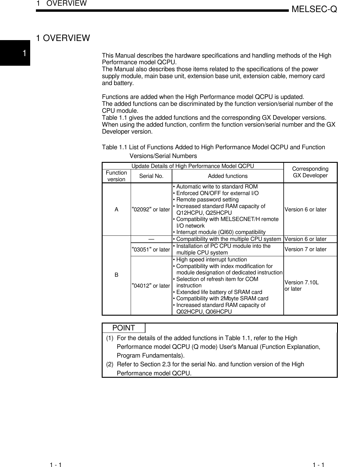
The latter half of 32 points l are similar. Sections 62 1031 and 113 d 092004 additions.

Q Series Dc Input Module Positive Common Type Qx41 Manualzz
Qy40p wiring diagram. Qx41 s1 qx42 s1 qx82 and q82 s1 memory card. Offcuts from entering the module during wiring. A20 a19 a18 a17 a16 a15 a14 a13 a12 a11 a10 a9 a8 a7 a6 a5 a4 a3 a2 a1 b20 b19 b18 b17 b16 b15 b14 b13 b12 b11 b10 b9 b8 b7 b6 b5 b4 b3 b2 b1. Spring clamp terminal block type output module qy10 ts qy40p ts qy80 ts spring clamp terminal blocks visually indicate the connection status. Qy10 ts qy40p ts qy80 ts spring clamp terminal block type output module mitsubishi programmable controller features 1. Manuals and user guides for mitsubishi electric qy40p.
Here is what is included. Impervious to vibration secured wiring connections. Can prevent the simultaneous opening of the output to control the peak current which is helpful for saving energy and reducing thee operation cost qy40p manual. Q2mem 2mbs sections 436 and 44 partial correction. Do not peel this label during wiring. Install our plc in a control panel for use.
Wiring method for common 32 pointscommon common terminal. Also by eliminating screws wiring and maintenance work is made easier. Connectorterminal block convertor module connection diagrams. I have put all of the wiring diagrams into a single pdf file to make life a little more simple and for some reason there was a 97 kb limit on zip files this time and it was 30 mb in my first post. Use the mitsubishi qy40p q series 16 point transistor 12 24 vdc 01 apoint 16 aco mmon sink type 16 pointsco mmon. Q12phcpu and q25phcpu digital input modules.
The above diagram shows the first half of 32 points f. We have 1 mitsubishi electric qy40p manual available for free pdf download. In addition the mixed control mode combined with the standard control and heating cooling control can be selected qy40p pdf. Qy40p qy41p qy42p qy50 qy68a c 102003 additions. Easy to confirm the connection condition 2. Before starting system operation be sure to peel this label because of heat dissipation.
Heating function at the same. 9 spring clamp. Ice machines q model service manual c 2003 manitowoc ice inc. Wire the main power supply to the power supply module installed in a control panel through a distribution terminal block. Reduced wiring and maintenance time with fluorescent indicators wiring connections can be easily confirmed. 4 pin cdi wiring diagram chinese atvjpg.
