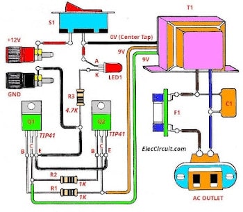
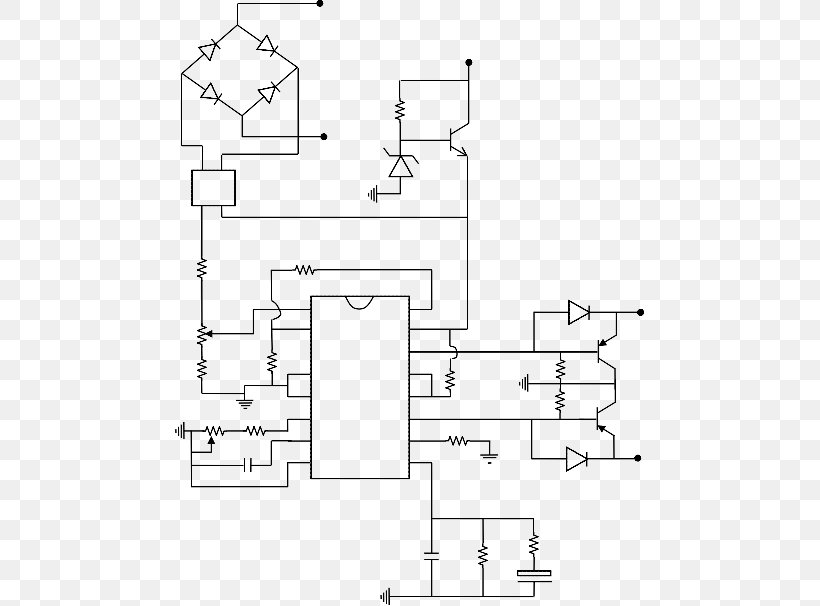
The waveform should be either sine wave or pure sine wave for high wattage inverters a 3 phase design would be fine while for small wattage inverter a single phase design would be fine. A wiring diagram is a simplified conventional photographic representation of an electrical circuit.
Oem Inverter Install Tacoma World
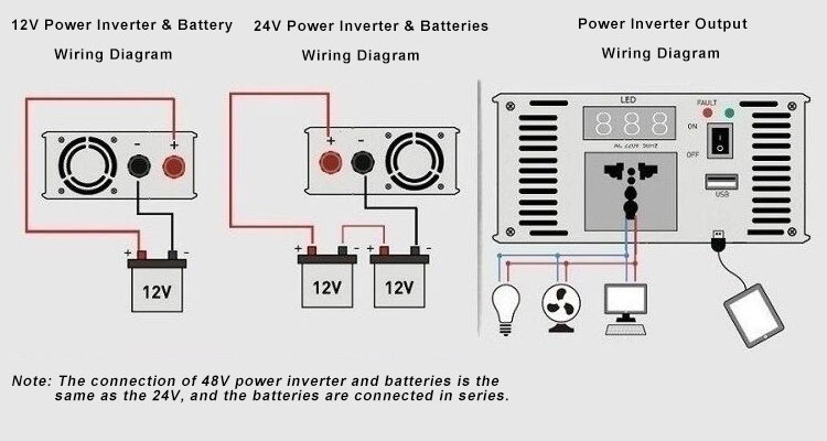
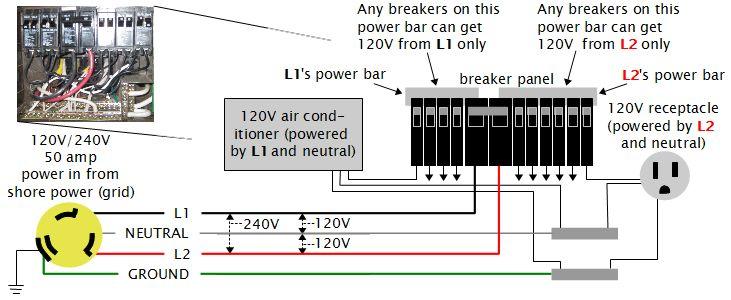
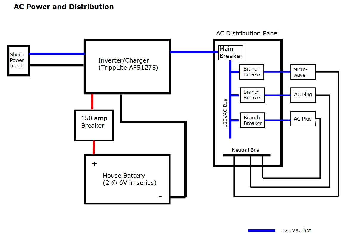
Power inverter wiring diagram. Each part should be set and linked to other parts in particular manner. A power inverter is simply an electrical device that converts direct current or dc to alternating current or ac. If not the arrangement wont work as it ought to be. Here is a picture gallery about rv inverter wiring diagram complete with the description of the image please find the image you need. Power inverter wiring diagram 2016 f150 power inverter wiring diagram 2017 f150 power inverter wiring diagram car power inverter wiring diagram every electrical arrangement consists of various different components. In simple words an inverter is used to provide alternating current ac from the direct current sources ie batteries and so on.
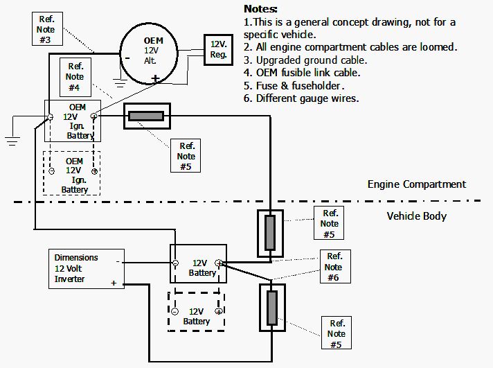
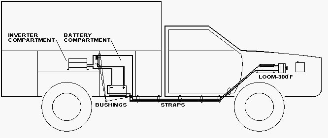
Figure 2 and 3 are diagrams for a smaller inverter 1000 watt or less where no auxiliary battery is being installed. It shows the components of the circuit as simplified shapes and the power as well as signal connections between the devices. Collection of rv inverter charger wiring diagram. Figure 4 is a diagram for a larger inverter 1000 watt or more where one or more auxiliary batteries are being installed. I need an electronic circuit diagram for an dc to ac power inverter with a range of 5kva to 30kva the inverter should be a transformer based power inverter. Power inverter installation magnum dimensions pertaining to rv inverter wiring diagram image size 583 x 328 px and to view image details please click the image.
An inverter can be used to operate electronic devices such as kitchen appliances tvs computers power tools and so on.


