File type description notes version size. Wiring diagrams of plc and dcs systems di do ai ao x liquid level control using flow loop control systems since liquid level can only change in a vessel if there is an imbalance of inlet and outlet flow rates would this system be practical to achieve stea.

Ariens 921017 004601 034999 Platinum 24 Parts Diagram For
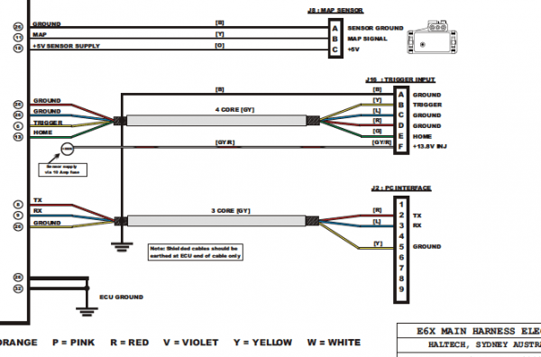
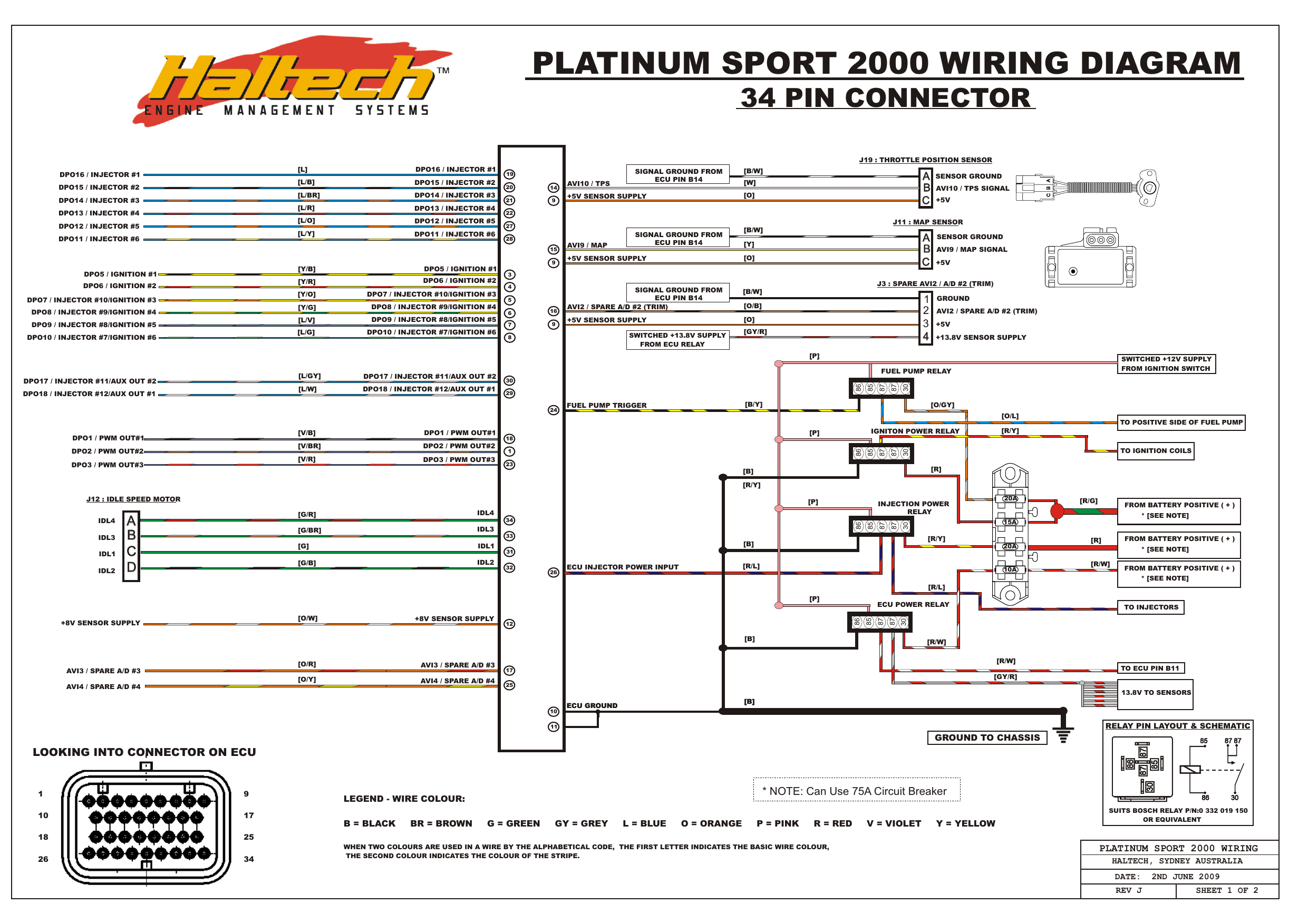
Platinum wiring diagram. Figure 5 shows the wiring for ratio metric bridge inputs. Field wiring connection diagrams. Platinum sport 2000 wiring harness with haltech fbx. Mount the sub base to the wall follow these steps to mount the 1050 control to the wall. At platinum wiring ltd we are dedicated to providing our customers with a friendly servicewe value your business and have made it our mission to provide reliable products and services in our customer driven approach. Photographic representations are usually images with labels or highly detailed illustrations of the physical parts.
Just how is a wiring diagram different from a photographic diagram. Connect the resistors r1 and r2 included in the provided wire kit across terminals 4 and 6 and terminals 1 and 8 respectively. Our courteous professional team is able to support a range of services to meet your requirements. Can wideband controller platinum. Turn off all power to heating and cooling equipment. Nissan 350z platinum plug n play red box user manual.
Wiring platinum 1050 mounting figure 3. The smartsiren platinum can control the signalmaster directional functions in federal signal lightbars ils systems and stick lights that are compatible with fs convergence network. File type description notes version size. It shows the components of the circuit as simplified shapes and the knack and signal connections amid the devices. If an existing thermostat is being replaced. Smartsiren platinum 3000b can be used with traditionally wired signalmaster units and both models can operate the latitude 3 wire signalmaster.
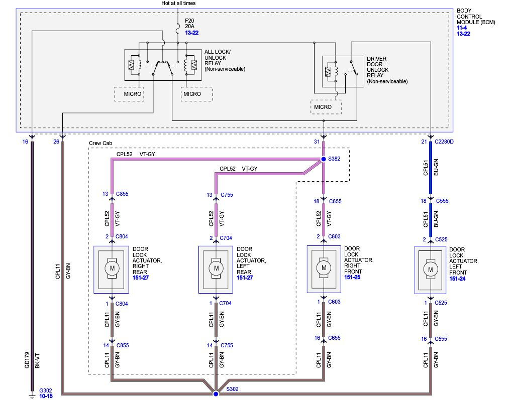
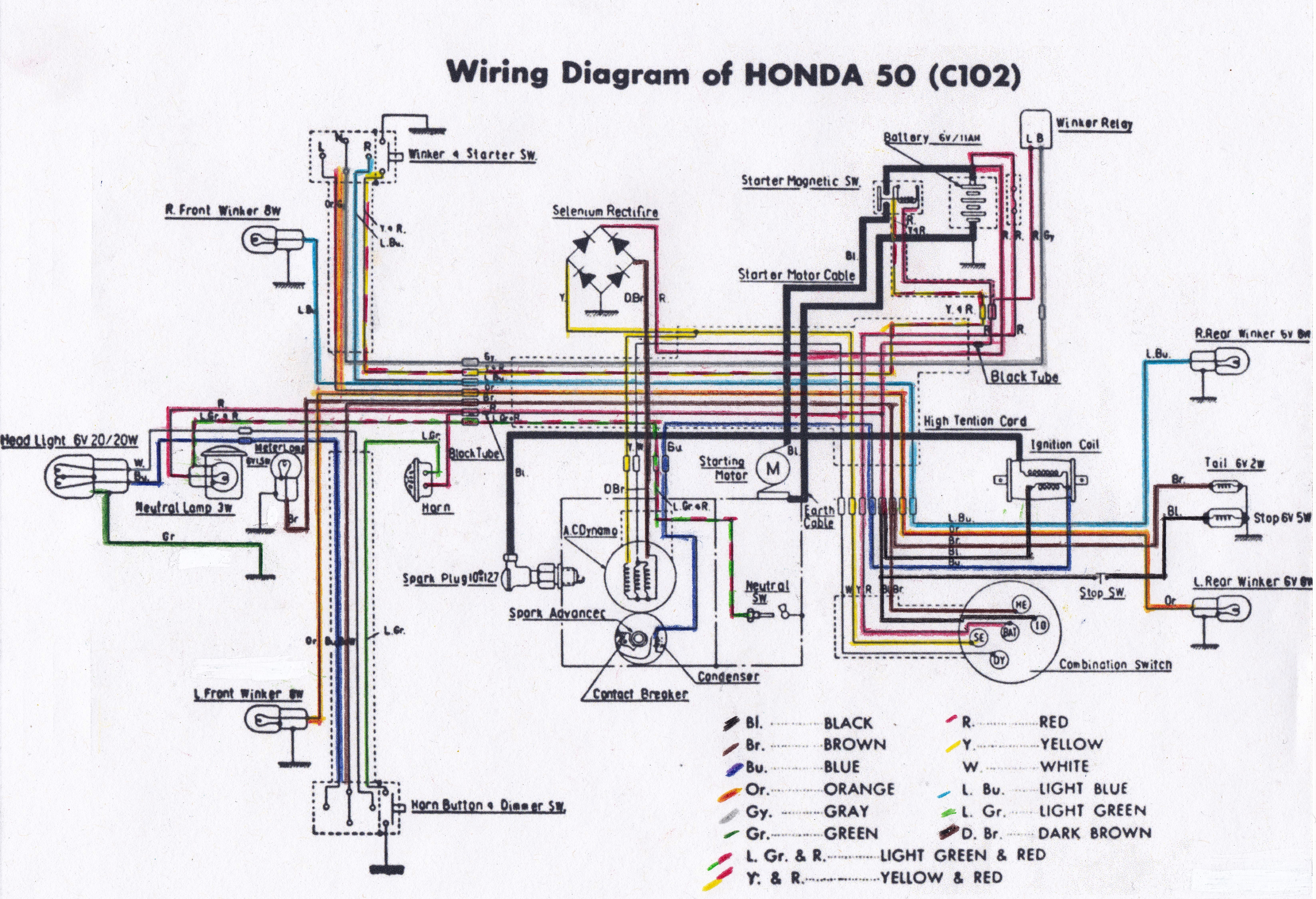
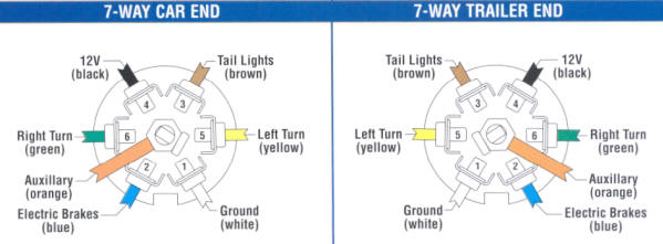
Pt cruiser wiring diagram wiring diagram is a simplified tolerable pictorial representation of an electrical circuit. 4 20 ma sensor wiring diagram. Refer to the platinum series users manual m5451 for more information on selecting the excitation voltage. Unlike a photographic diagram a wiring diagram utilizes abstract or streamlined shapes and lines to reveal parts.
