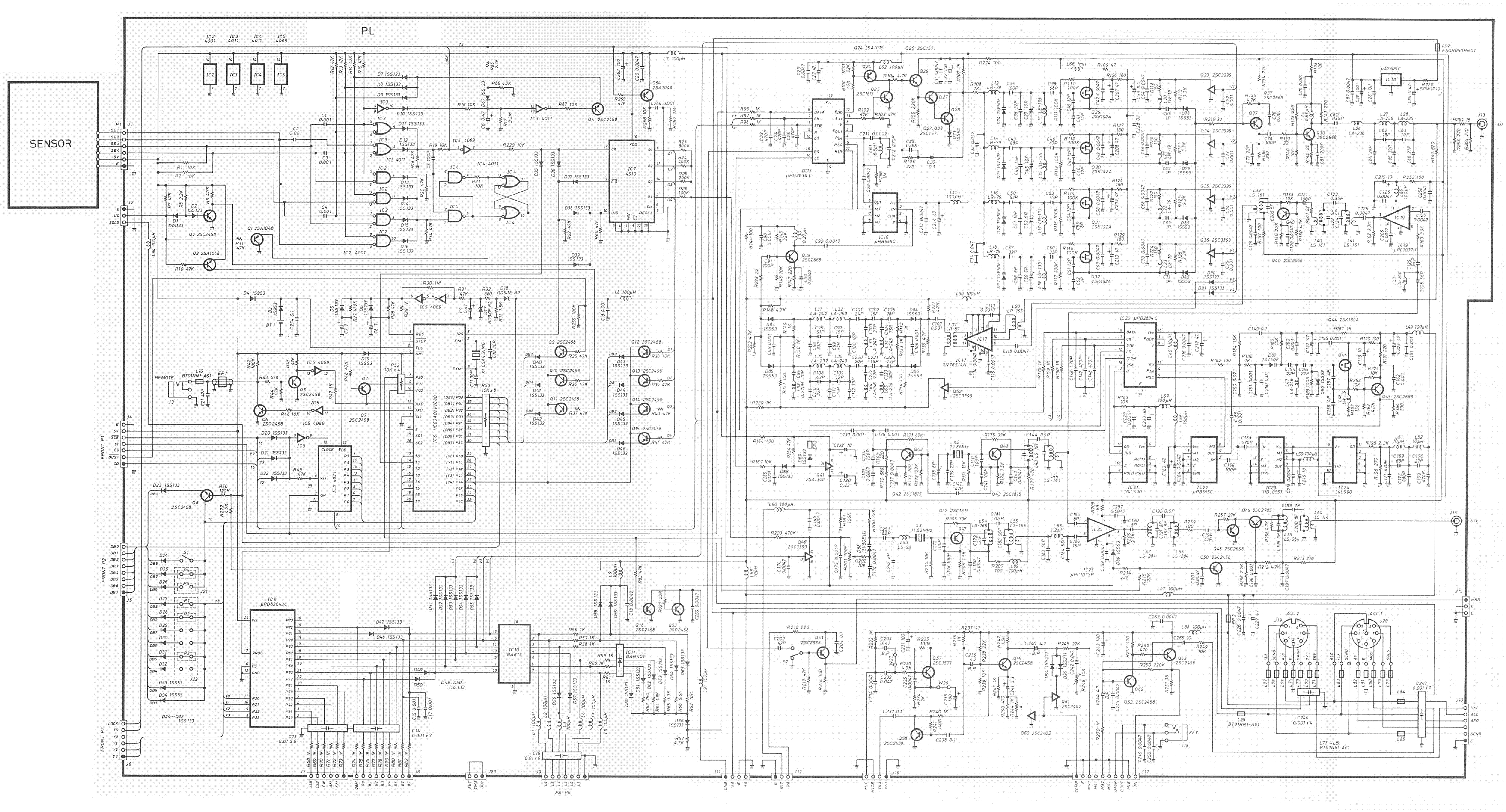
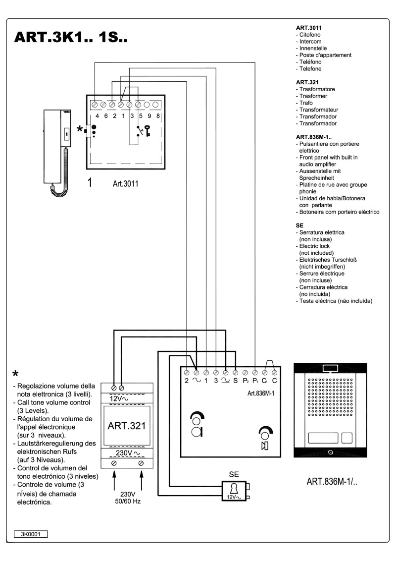
Shown on wiring diagram since the situation is not always improved by adding it. The common wires connecting to terminals 1 2 3 e and 5 must show open circuit when tested with.
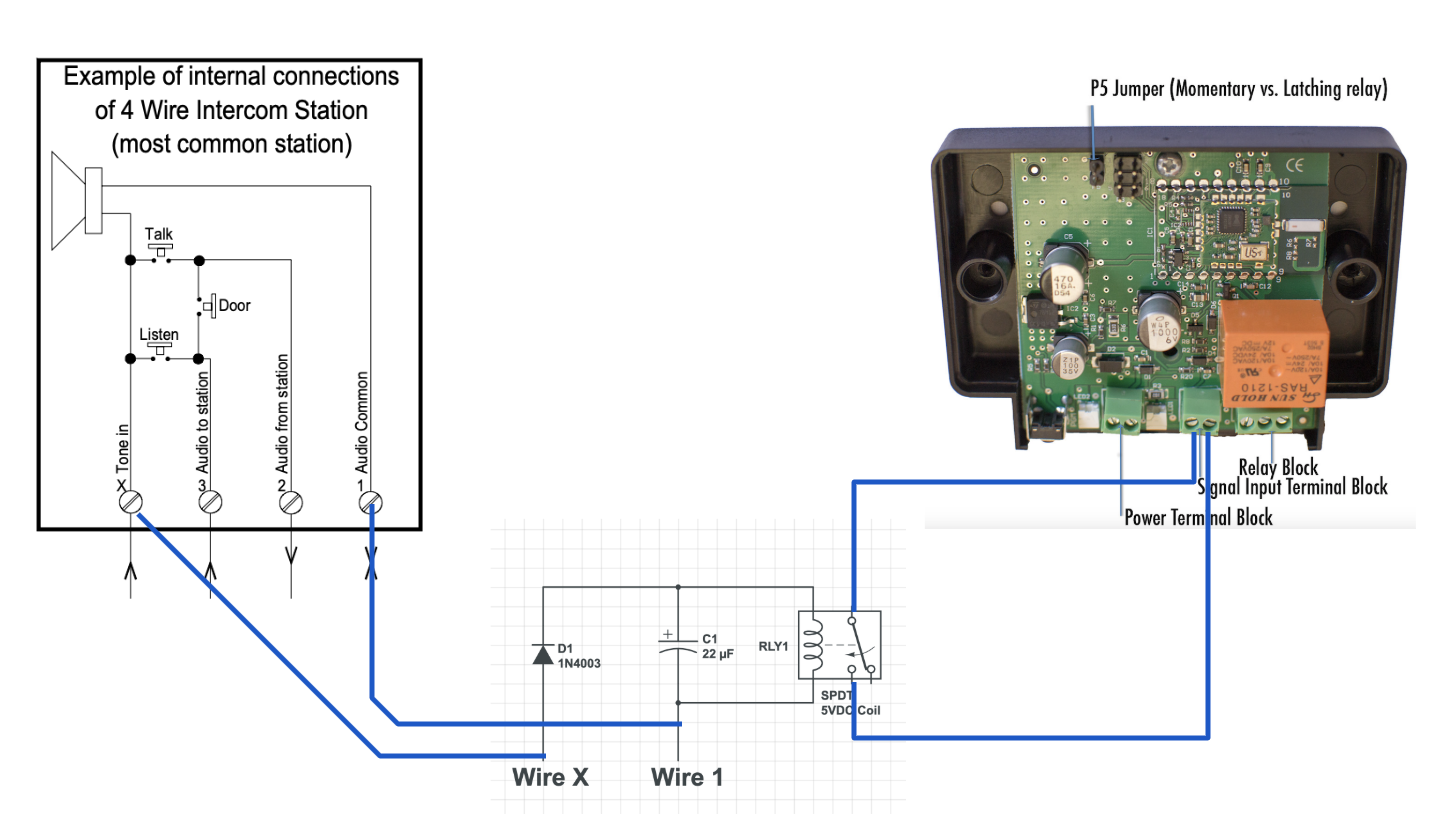
Connecting An Apartment Door Buzzer To A Smarthome Hub By
Pk543a wiring diagram. Pka apartment intercom system amplifier wiring guide pka amplifier with 543 wire apt. If oscillation persists con nect a model 15 mfd non polar capacitor across terminals a and g on the pk 543 amplifier. Easy to read installation and wiring guide lines for the tektone pk543a apartment intercom amplifier. All low voltage wiring is 22 awg unless otherwise noted. Make connections as shown on the wiring diagram for the amplifier being used. Check for shorts andor grounds before connecting transformer to ia543 pk543a amplifier.
If problems persist consult factory. Observe the following notes. Download pk543a wiring diagram. As per figure 1pk543a wiring diagram. Observe all local and national electrical and building codes. Do not apply power to the transformer primary until the entire system has been installed and checked for shorts and grounds.
Stations wiring diagram 8 pages. Tone back to entry panel when a call button is pressed set sw3 to on right to activate this feature use warble tone zw terminal technical support 866 503 2298 call from the job site for troubleshooting tricks. Pk543a tektone intercom ampilfier wiring diagram. Pk543a tektone apartment intercom entry system control amplifier. Oscillation check wiring step 4 on page 1. Install transformer at least 3 feet 1 meter away from ia543 pk543a amplifier.
Designed for use with 3 4 or 5 wire apartment remote stations providing amplification control and power circuits needed to operate a complete apartment intercom entry system.

