More electrical tips and diagrams wwwaboutelectricitycouk like. This video is a step by step.

Motion Sensor Wall Switch For Sale In Stock Ebay
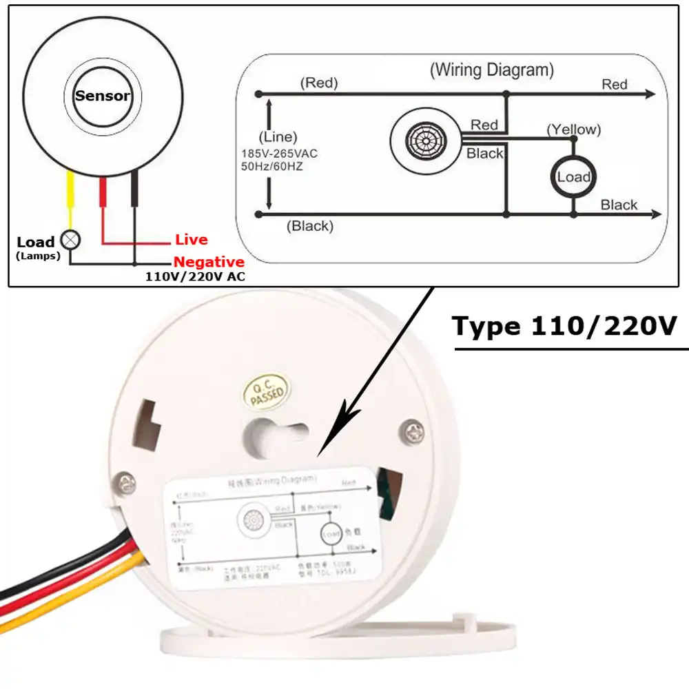
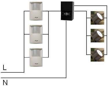
Pir light switch wiring diagram. With the left switch on the pir is powered and will activate the lights when motion is detected. There are some limitations to this system. The hot and neutral terminals on each fixture are spliced with a pigtail to the circuit wires which then continue on to the next light. Pir wall switch wiring diagram wiring diagram motion sensor wiring diagram in addition wiring diagram provides you with the time frame by which the projects are to become finished. The left switch is the main onoff. Multiple light wiring diagram.
If not the structure will not function as it ought to be. This diagram illustrates wiring for one switch to control 2 or more lights. Wiring a motion sensor light diagram motion sensor light wiring diagram australia wiring a motion sensor light diagram wiring a motion sensor light diagram uk every electrical arrangement is composed of various diverse pieces. In this video you will see how to wire pir sensor light in the ukit will also show you internal wiring of pir sensor and light. To read a wiring diagram first you need to know what basic elements are consisted of in a wiring diagram and also which photographic symbols are used to represent them. L1 on that switch connects to com on the other switch and to l at the pir sensor.
How to wire pir motion sensor light switch correct wiring probably saves an expensive pir sensor from an irrecoverable malfunction and annulment of any warranty terms. No wiring is necessary to control existing lights. Each component should be placed and linked to other parts in specific manner. Some wiring may vary however this is the most common wiring scenario for a 120 volt light fixture. The source is at sw1 and 2 wire cable runs from there to the fixtures. Incoming line connects to com on one switch.
It sends a radio signal to a receiver that switches on a light. Wireless motion sensor lights a wireless sensor works like the remote control for a garage door opener. Electrical wiring at the light fixture is typically made by connecting together the wires of the same color which are commonly black white and the bare ground wire or green ground wire. In the off position the lights and sensor are off permanently. You will be in a position to know specifically if the tasks ought to be finished which makes it much easier for you to properly manage your time and effort. The typical elements in a wiring diagram are ground power supply wire and connection outcome gadgets switches resistors reasoning gate lights etc.
Just screw the receiver into a light socket and mount the sensor anywhere you like. L1 on the second switch connects to sl switched line on the pir and also to the lighting.


