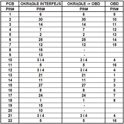
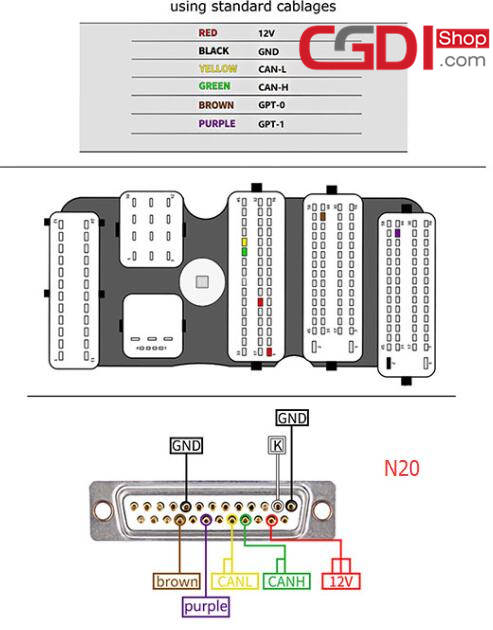
In accordance with wiring diagram for obd2 port to usb you will find only four wires used in the cable. If the vehicles onboard diagnostic system detects a malfunction a dtc corresponding to the malfunction is stored in the vehicles computer as well as realtime data.

Az 3204 Obd2 Connector Diagram Free Diagram
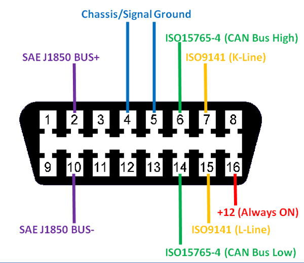
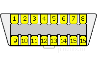
Odb2 wiring diagram. It follows 2 wire can protocol at 1mbps speed. Iso 9141 l line. Obd i begins standardized dtcs obd ii adds specific tests to determine the vehicles emission performance obd iii adds more features and is in the regulatory development phase. This is the can low pin. The red one is to get sure cable with dc ability of 5 volts. With this kind of an illustrative guide you will be able to troubleshoot stop and full your assignments easily.
Not merely will it help you accomplish your required outcomes more quickly but in addition make the entire procedure simpler for everyone. Obd2 wiring diagram youll need an extensive skilled and easy to understand wiring diagram. It follows 2 wire can protocol at 1mbps speed. This is the can high pin. Typically it uses black green white and red cable colors. Iso 9141 k line.
Typically it uses black black red and white cable colors. It follows asynchronous serial communication protocol this pin is the k line. The red one is to get sure wire with dc power of 5 liter. Black wire serves as ground exactly like in any other apparatus. Black cable serves as floor just like in every other device. Mini usb wiring schematic wiring library mini usb wiring diagram wiring diagram consists of each illustrations and step by step directions that might permit 4 wire o2 sensor wiring diagram september 13 2018 april 12 2020 wiring diagram by anna r.
In accordance with usb to obd2 cable wiring diagram there are only four wires used inside the cable.

