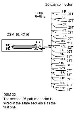
T and r represent station connections and should not be confused with tip and ring on external lines. Connecting the wiring 87 connecting the wiring for a compact ics 87 connecting the wiring to the distribution panel 88 wiring charts 88 bri wiring charts 96 installing norstar telephones 102 installing the emergency telephone 102 installing the device that uses the i ata 103 installing business series terminals 104 installing norstar telephones 106.
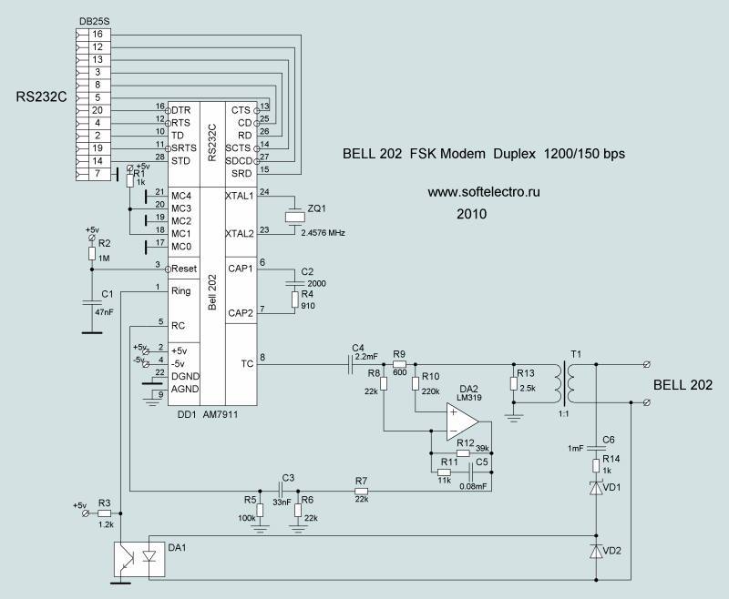
Exchange Interface Bell 202
Norstar compact ics wiring diagram. Norstar ics wiring charts. I have the equiptment and need to know how to wire from the 66 block to the customer premise. Ics telephone extns wiring chart. If the ics ics telephone and auxiliary ringer wiring chart. Any help will be appreciated. Each telephone port on the ics has a b1 dn and a b2 dn.
Devices such as the business series terminals and norstar telephones use only the b1 dn. Station connections are non polarized. 1 2 and 3 as shown below. The following wiring charts describe the three ics connectors. Connecting the wiring 89 p0603539 02 compact ics 61 installer guide b1 and b2 directory numbers dns norstar has a b1 and b2 channel for transmitting voice and data. I need the wiring schematics for norstar compact ics 40 guest visitor op 9 aug 01 2239.
Ics telephone extns wiring chart. The existing phone lines coming in. Emdisa trunk cartridge wiring chart upgrading to compact ics 57. P0992669 03 compact ics 60 installer guide installing the expansion cartridge 81 connecting the wiring 83 connecting the wiring to the distribution panel 84 wiring charts 84 bri wiring charts 92 installing norstar telephones 98 installing the emergency telephone 98 installing the device that uses the i ata 99 installing business series. Load that the norstar ics requires from a telephone line. Norstar ics wiring charts.
1 2 and 3 as shown below. The following wiring charts describe the three ics connectors.
