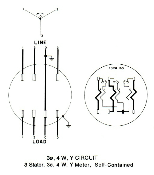
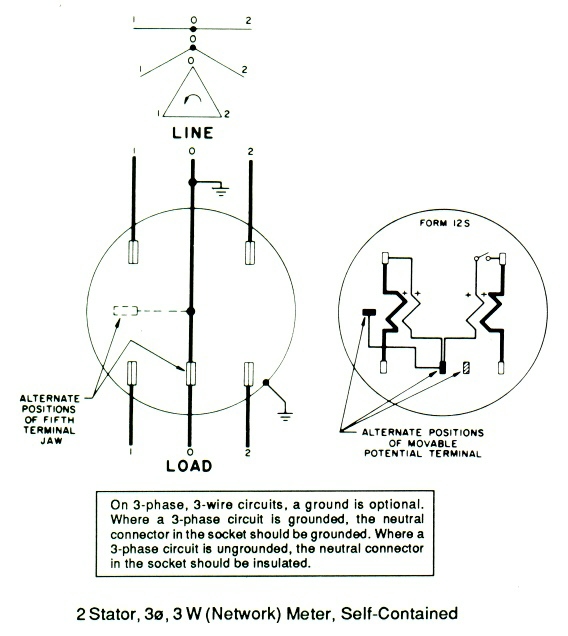
The form 9s meter is one of the most commonly used meter forms. Click here to view and print the full size diagram.

Wiring Diagrams Archives Learn Metering
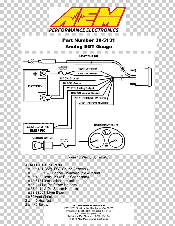
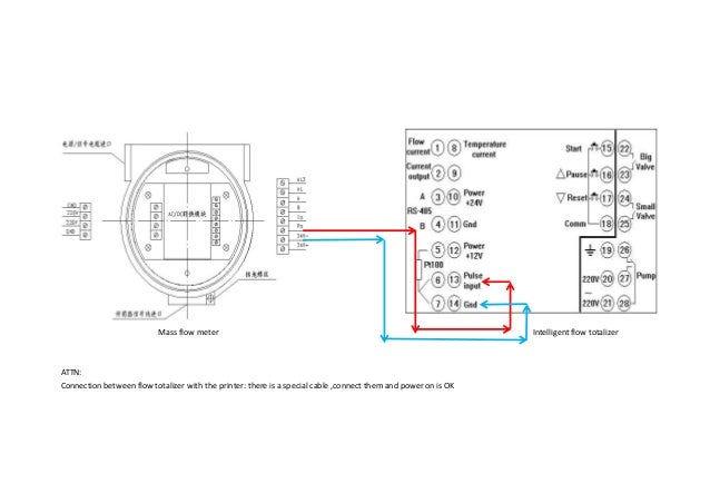
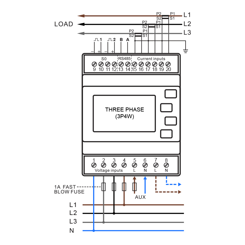
Meter wiring diagram. Wiring representations are made up of 2 points. S0 as you begin to study the wiring diagram i want to make note of a few things. Also it can also be found on temporary services. One of the most requested items of information that we receive is for wiring diagrams for the meters we sell. That is because there is no universally accepted color code. Here we installed a gm factory match transmission temp boost and egt pyrometer on a tow truck equipped.
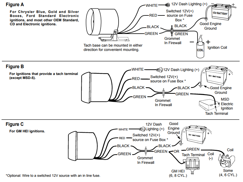
There is also a 6 gauge ground wire that links the neutralground connection on the meter to the grounding rod. About the form 9s meter wiring diagram. Form 2s need a meter for a 120 volt circuit. If ammeter shows a positive charge when starter is engaged reverse connections on back of ammeter. It is also found on large businesses with the same requirements. Find vehicle specific installation information.
Reconnect the battery ground cable. Be aware that these are general diagrams using standard test switches which may not match some utility standards in their configuration and are for reference only. With and without cts and pts for wye delta and network circuits. Icons that stand for the parts in the circuit as well as lines that stand for the links between them. 02052018 2003 gm duramax boost egt and transmission temp. Connect ammeter lamp 60 0 60 i only to existing instrument panel lighting circuit.
The form 4s meter is a transformer rated also known as a ct meter and is typically installed on large residences who have 400 amp or larger services. 3s wiring diagram 1 ph 2 wire 1 pt 1 ct glems would like to thank and acknowledge the use of the following meter connection diagrams from dr. This diagram shows how to wire it for 120v. Single phase form 2s for 240v circuit. Order our 240 volt meter. Single phase form 2s for 120v circuit.
First is that the colors that i chose were chosen at random. Meter wiring diagrams provided by tesco ansi meter wiring diagrams the great lakes electric meter school glems began in 1989 with a committee composed of members of electric utilities electric utility manufacturers and experts in the utility field. This is the portion of the meter that feeds the main service panel or the electrical disconnect. Search through our list of wiring diagrams to find the right one for your job. This page contains circuit type and wiring diagrams for all the form s of meters sockets and pans. A wiring diagram is a type of schematic which utilizes abstract pictorial signs to show all the affiliations of elements in a system.
As with the line connection the load connection has the two hot feeds as well as a center neutral connection. Find product manuals and wiring diagrams for your auto meter product.


