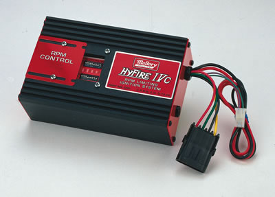
Mallory hyfirefi vi electronic ignition controls are not compatible with distributorless systems or positive ground applications. Collection of mallory ignition wiring diagram.

Ac 2555 Wiring Diagram Mallory Comp 9000 Wiring Diagram
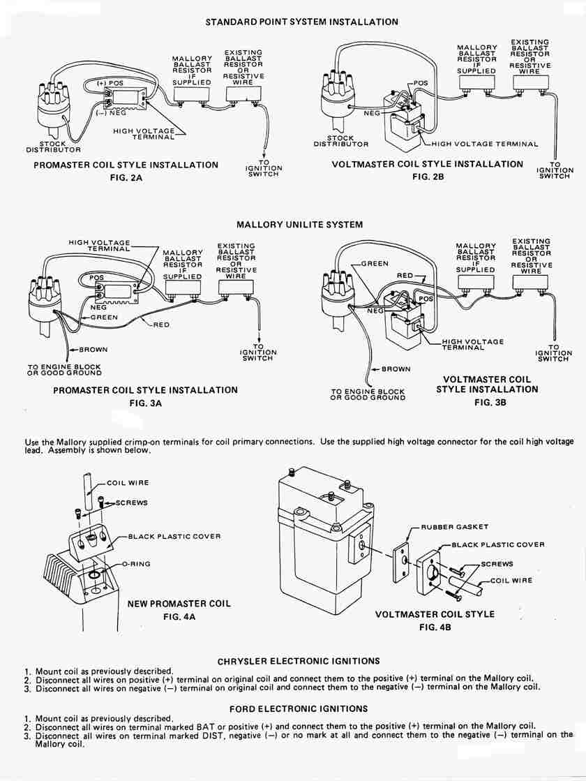
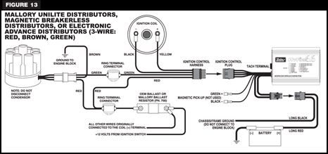
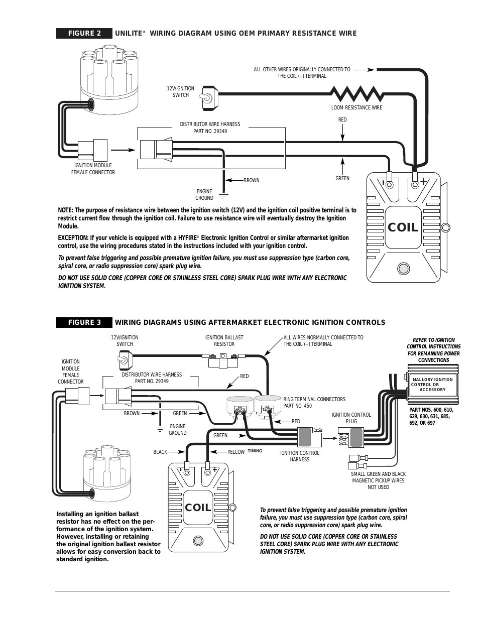
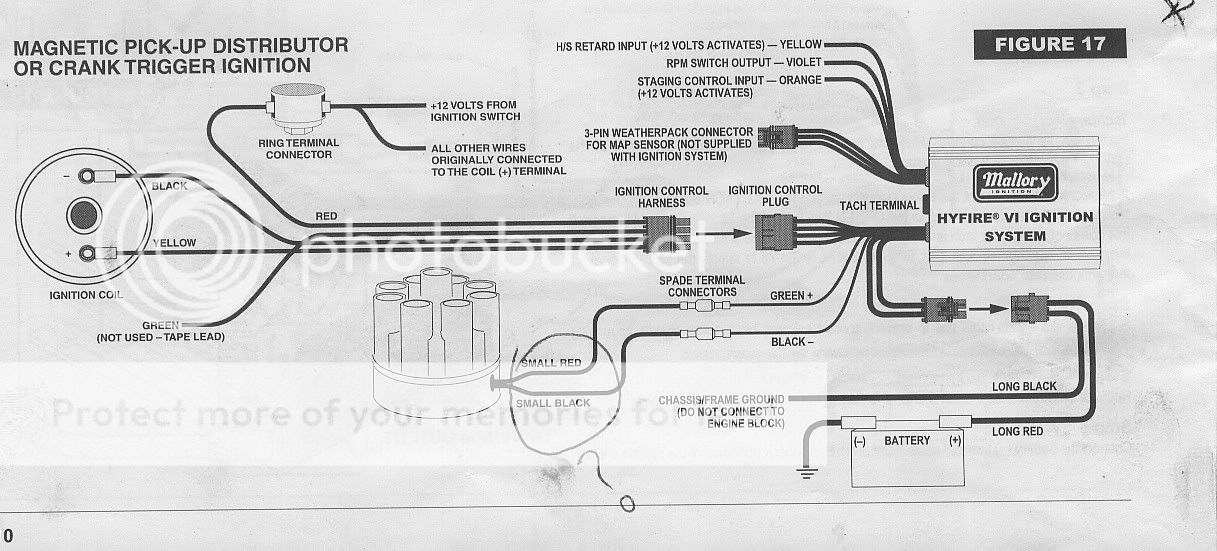
Mallory hyfire wiring diagram. It shows the components of the circuit as streamlined forms as well as the power and also signal links between the tools. Mallory hyfire 6a wiring diagram note. A wiring diagram is a simplified standard pictorial depiction of an electrical circuit. Installation instructions 3 mallory wwwmallory ignitioncom 915 857 5200 fa 915 857 3344 ballast resistor. Mallory electronic igni distributors magnetic or electronic advance three wirered brown durasçark ssi. Do not use mallory s pomaste coil pn tachometers the yellow wire on note.
Recommend mallorys promaster coil pn or mallorys all of the wires of the hyfire. Srvu plug edule. 692 will not work properly with odd fire or semi. Do not use solid core spark plug wires with the hyfie 6a ignition. Mallory hyfire ignition wiring diagram file pdf book only if you are registered here. The rpm limiter in the hyfire fi ivc part no.
Mallory hyfire wiring question nastyz28 com. Mallorys promaster coil pn can also be used as well as most stock coils or aftermarket coils the yellow wire on the hyfire 6a ignition control provides a trigger signal for use the chart at right as a starting point. The uniliteignition system works with most stock ignition coils and aftermarket high performance ignition coils. For optimum performance use a mallory promastercoil part no 29440 or 29625 or mallory chrome electronic ignition coil part no. When you select a coil for any high power cd ignition box like the mallory hyfire cd boxes the mallory hyfire cd boxes must always use a coil with less than 1 ohm of primary resistance. If your vehicle has a ballast resistor in line with the coil wiring it is recommended to bypass it.
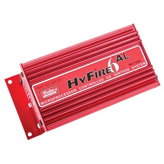
Mallory hyfirefi iv electronic ignition controls are not compatible with distributorless systems or positive ground applications. 685 will not work properly with odd fire or semi even fire v6 applications. Double throw switch for a single mag installation see wiring diagrams. 1 hyfirefi vi electronic ignition control part no. Plug pcxup can nectar 100. 6852m 6 a and 6853m 6 al installation instructions form 1522tl general information the features of the hyfire 6 a and hyfire 6 al are the same with one exceptionthe hyfire 6 al includes a single stage.
Of terminals on both ends of the module and follow the corresponding diagram. The rpm limiter in the hyfire fi vi part no. Ylinoer or cylinder hyfire at 3rli ignition system. Parts included in this kit. A word of caution here extending magnetic pickup leads can introduce emi. Harness the manor stem underneath distributor.
Routing wires the hyfire wires should be routed away from direct heat sources such as exhaust manifolds and headers and any sharp edges.







/Saab%20900%20Wiring%20diagram%20(early%20models)%20part%201.jpg)
