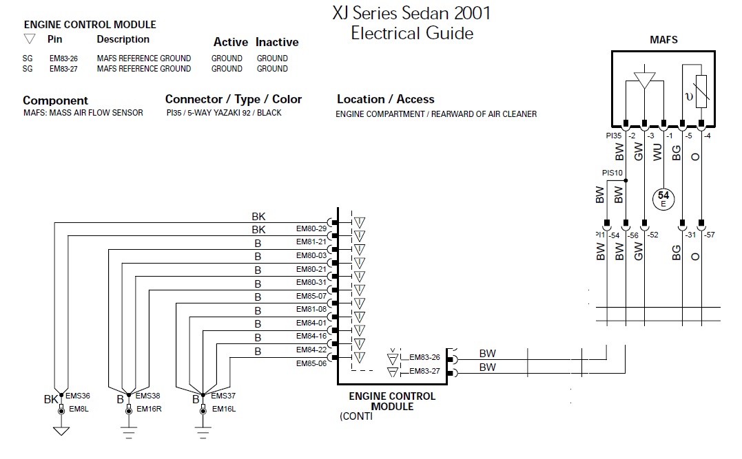
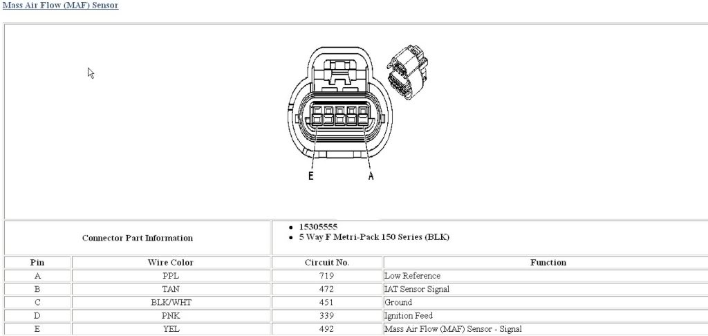
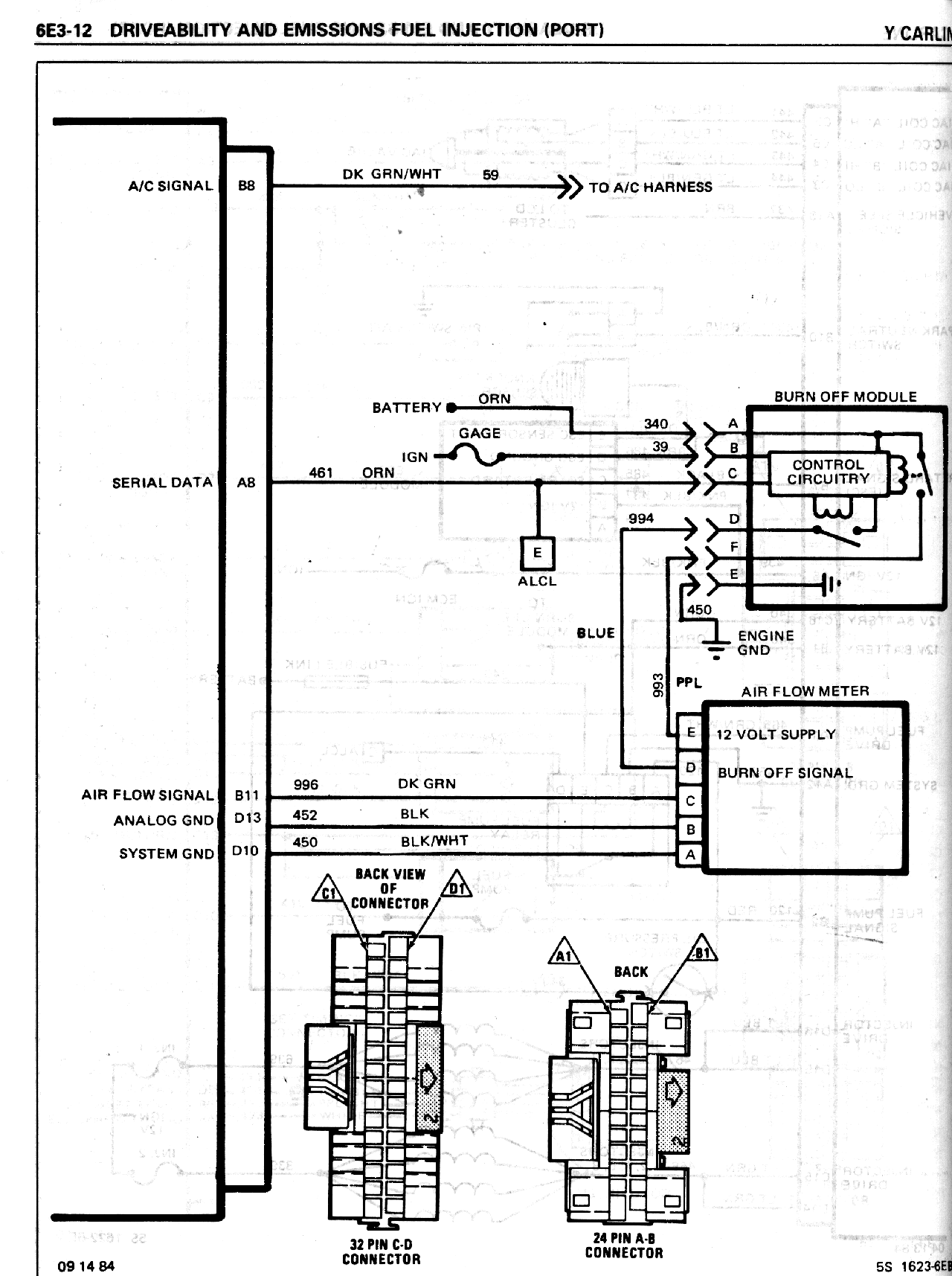
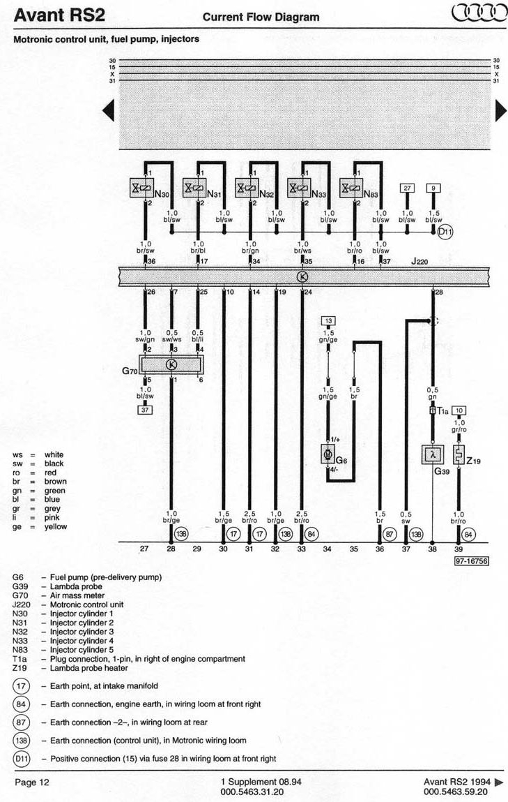
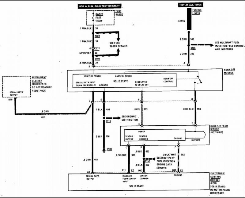
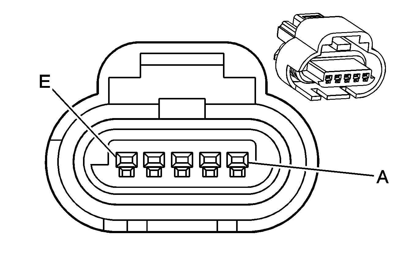
The primary components of the maf sensor are thermistor a platinum hot wire and an electronic control circuit. The following schematic shows a typical circuit diagram of the mass air flow maf sensor system.

Wilbo666 Toyota Air Flow Sensors
Maf wiring diagram. Having trouble locating a maf. If the oxygen sensor wiring diagram. If not the structure wont work as it ought to be. I need color wires and pin location for a 5 wire denso maf sensor. Mass air flow maf sensors 32 manual cautions when working around the air bag components or wiring. The mass air flow sensors converts the amount of air drawn into the engine into a voltage signal.
Mass air flow sensor wiring schematic. F150 f250 f350 mustang crown victoria. Maf wiring diagram ford maf wiring diagram ka24de maf wiring diagram ls1 maf wiring diagram every electric arrangement is composed of various unique components. 7motor vehicle maintenance repair stack exchange is a question and answer site for mechanics and diy enthusiast owners of cars trucks and motorcycles. Wiring diagram for a 08 s80 32l non turbo. Maf sensor gets power from the pcm power relay red wire.
Each part ought to be placed and connected with different parts in particular way. The lt blured wire outputs the maf signal to the pcm. Maf sensor wiring diagram 19971998 1999 ford 46l 54l. Two wires got pulled out doing a.
