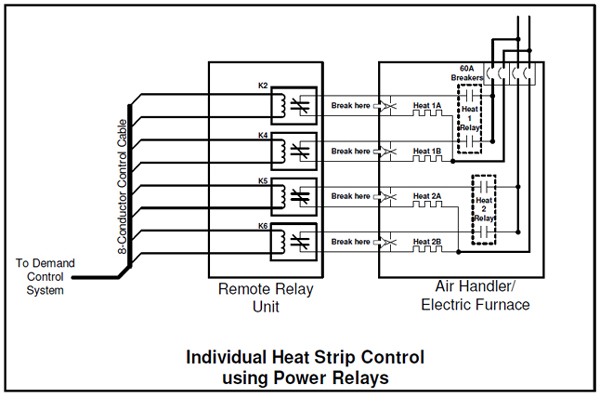
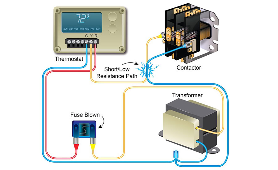
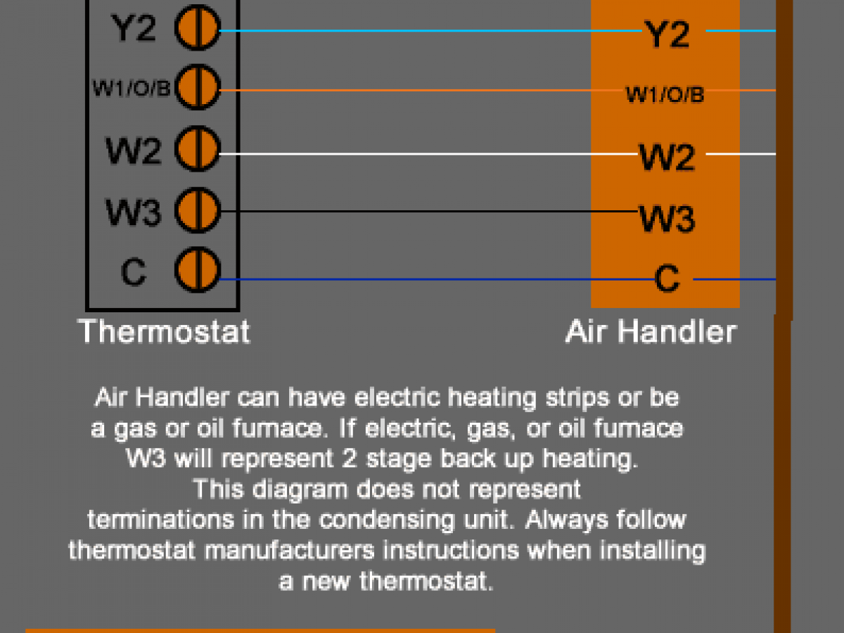
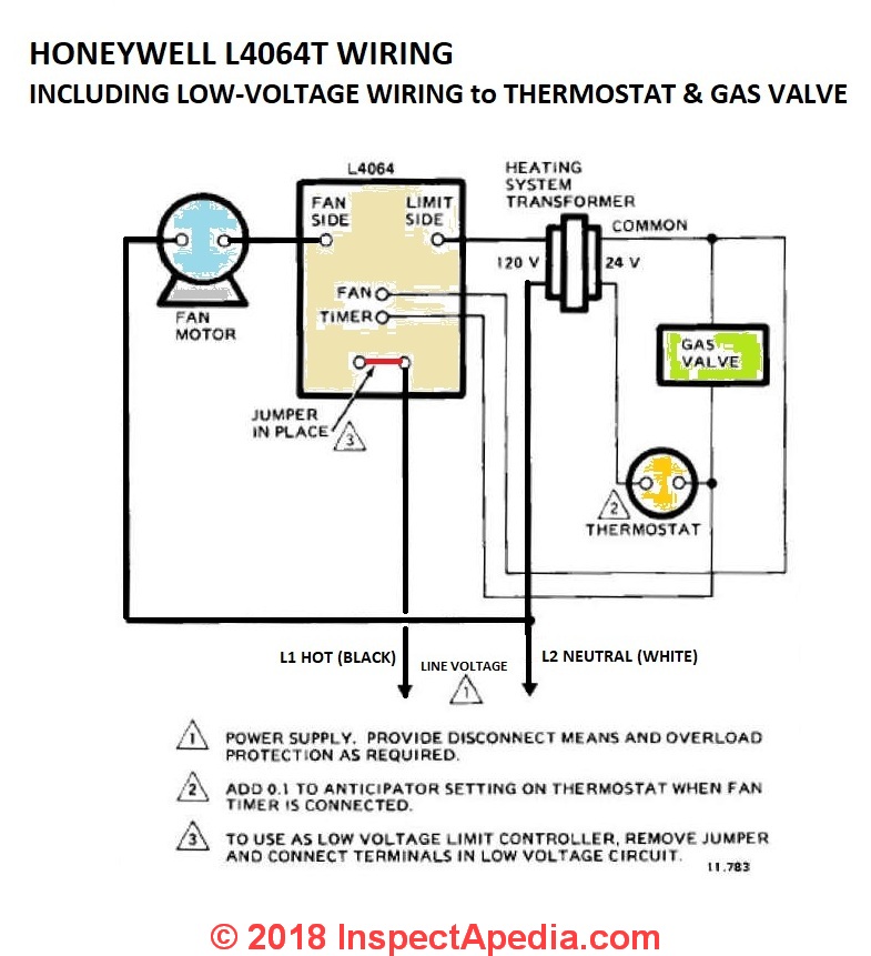
How to wire an air conditioner for control 5 wires the diagram below includes the typical control wiring for a conventional central air conditioning systemfurthermore it includes a thermostat a condenser and an air handler with a heat source. This diagram is to be used as reference for the low voltage control wiring of your heating and ac system.

Low Voltage Or High Voltage Heating What S The Difference
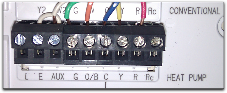
Low voltage thermostat wiring diagram. My paperback and e book. Always refer to your thermostat or equipment installation guides to verify proper wiring. Notesome ac systems will have a blue wire with a pink stripe in place of the yellow or y wire. This additional terminal is labeled g in the thermostat. Figure 1 is a circuit diagram showing the simplest possible known thermostat control system for heating and cooling operation of an ac and furnace or. In the most basic system this functionality is provided by use of a fan center relay and the low voltage wiring to the thermostat now will require a minimum of three wires for heat only units and four wires for heat cool fan for control.
Product pro1 iaq low voltage thermostatprog heat pump t725. Use our menu to the right to find helpful articles such as thermostat wiring diagrams low voltage circuits for hvac how to wire an air conditioner for control control board troubleshooting and thermostat troubleshooting. The thermostat controls the operation of the heater compressor and blower as shown in figure 1. Low voltage thermostat wiring. Basic home wiring diagrams. Low voltage transformer is connected through the thermostat to each control relay.


