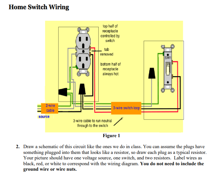
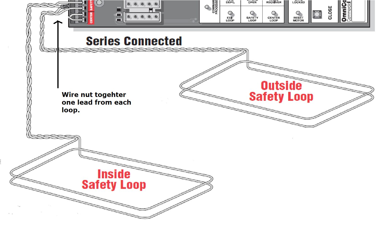
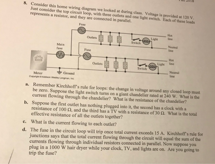
This diagram illustrates wiring for one switch to control 2 or more lights. Wiring diagram of loop powered isolator with external powered 4 wire transmitter.

Switch Loops
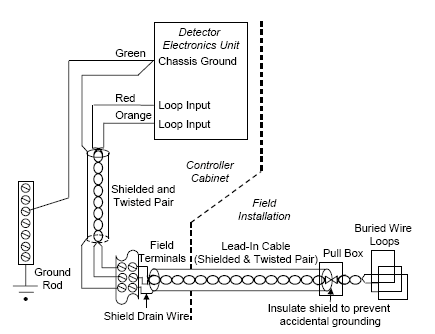
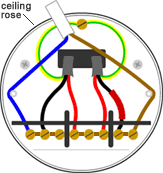
Loop wiring diagram. 1a this is the most common loop in wiring arrangement you are likely to see. One cable lne either from the mains board or the last ceiling rose one cable lne out to the next ceiling rose and one cable lsl e that goes to the wall or pull switch within that room. Loop drawings can be customized per customer taste although certain minimum standard information is required to be included in loop sheets. The ceiling rose should be wired as shown below. Mark the white wire at each end with black tape or black paint to indicate it is hot. Loop diagrams are the most detailed form of diagrams for a control system and thus it must contain all details omitted by pfds and pids alike.
This is a typical wiring diagram of a loop powered signal isolator get energy from the input and 4 wire transmitter detailed parameters of loop powered signal isolator ato s sinir 502e are in the product page. The source is at sw1 and 2 wire cable runs from there to the fixtures. These set of drawings are more detailed than process and instrument diagrams pids. It shows three cables. Next the incoming white neutral wire is attached to the light fixture as usual and the black wire from the switch is connected to the light fixture. The hot and neutral terminals on each fixture are spliced with a pigtail to the circuit wires which then continue on to the next light.
Loop in as the red wire from the feed cable the black wire coming back from the switch is connected. Explanation of above picture. One way lighting circuit using loop in ceiling roses. Instrument loop diagrams are also called instrument loop drawings or loop sheets. Basics of instrument loop diagrams. To make a switch loop connect the incoming hot black wire to the white neutral wire that runs to the switch.
Line diagram of a one way lighting circuit using loop in ceiling roses fig 1.
