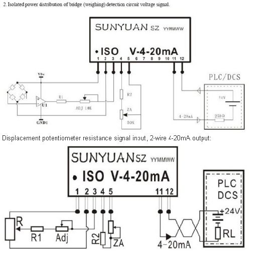
Wiring diagram of loop powered isolator with external powered 4 wire transmitter. Dashed lines in instrument drawings represent individual copper wires rather than whole cables terminal blocks where wires connect are represented by squares with numbers in them.

Loop Powered Isolator
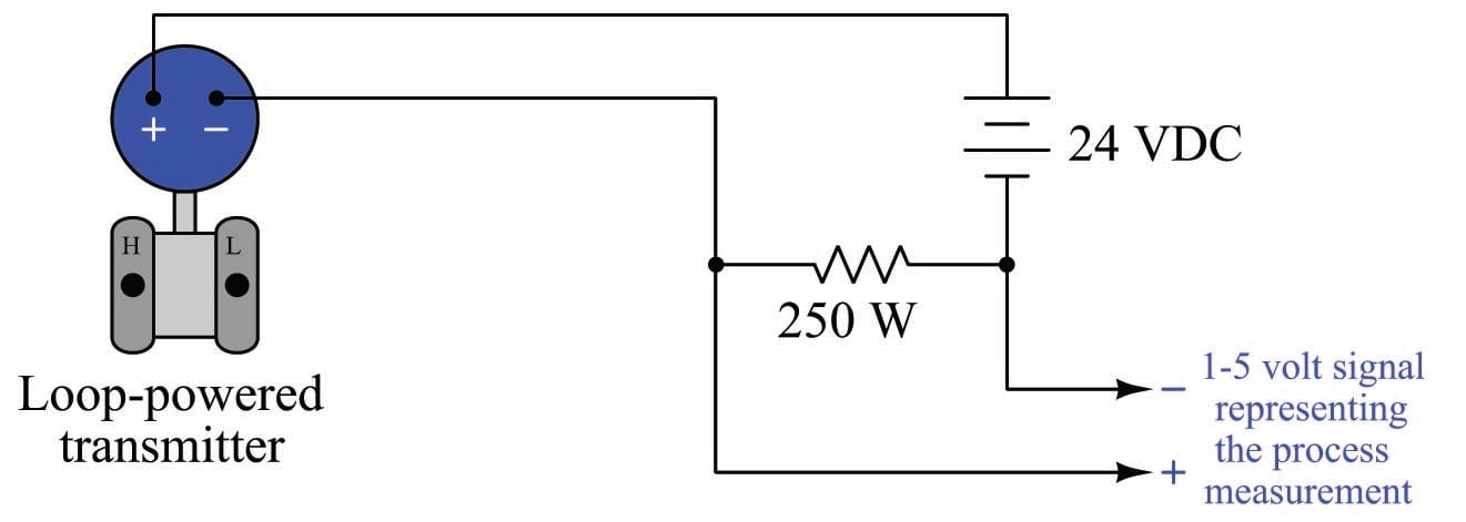
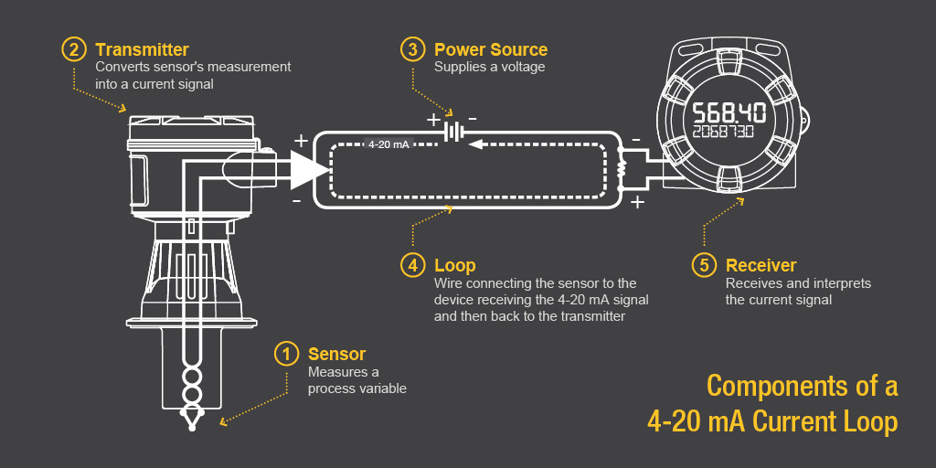
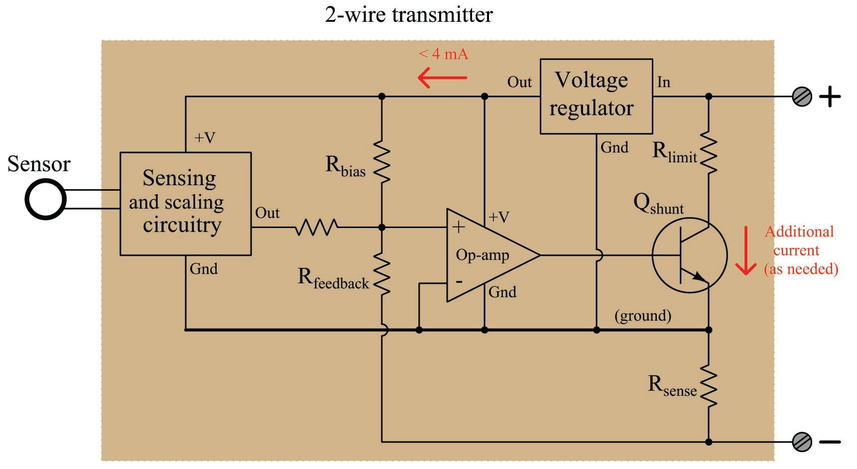
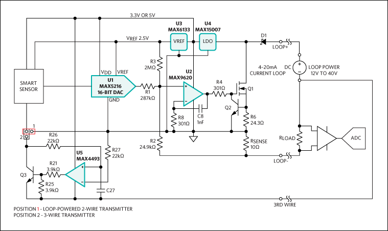
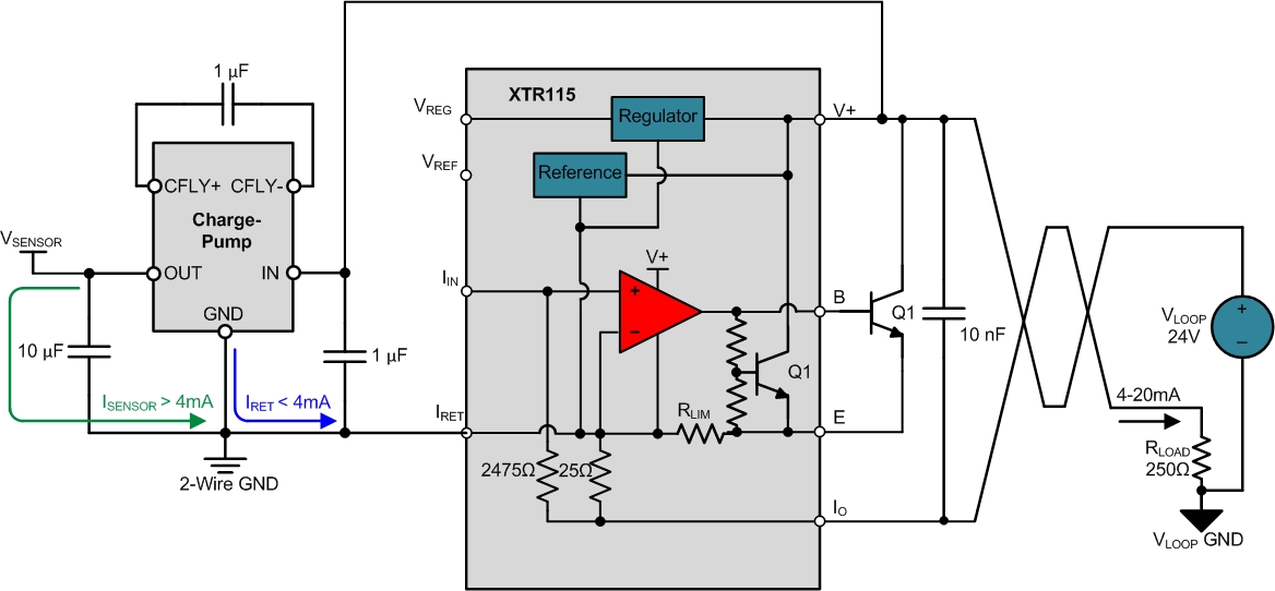
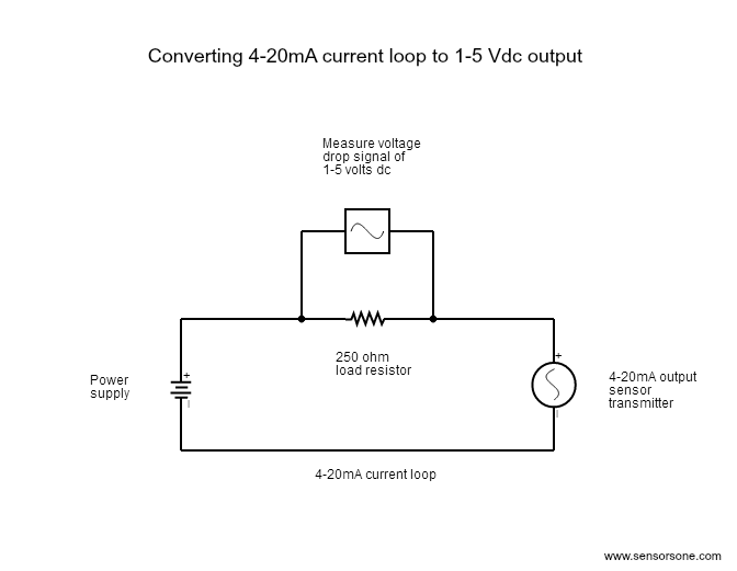
Loop powered transmitter wiring diagram. The base of the triangle is labeled r and refers to receiver. A separate power supply is required for both the transmitter and control panel. Introduction to the two wire transmitter and the 4 20ma current loop the left side is labeled t and refers to transmitter. A transmitter analog output loop contains the transmitter power supply and the receiving device such as a plc. Two wire loop powered transmitters. A 4 wire transmitter has 2 wires connected to a power supply and 2 signal wires connected to the plc.
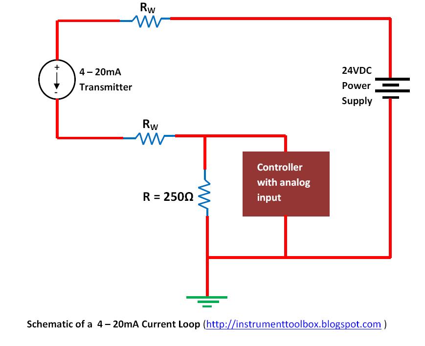
The right side of the triangle is labeled i and refers to the source of current or the power supply. Each instrument bubble in a loop diagram represent an individual device with its own terminals for connecting wires. The actual wiring between the transmitter and the power supply depends upon whether it is a 2 wire or a 4 wire type. The current allowed by the transmitter is called the loop current and it is proportional to the parameter that is being measured. As shown in the diagram above current supplied from the power supply flows through the loop wires with resistance rw to the transmitter and the 4 20ma transmitter regulates the current flow within the loop. This is a typical wiring diagram of a loop powered signal isolator get energy from the input and 4 wire transmitter detailed parameters of loop powered signal isolator ato s sinir 502e are in the product page.
This configuration supplies power and 4 20ma signal over a two wire loop connection between the transmitter and the control panel.


