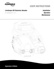
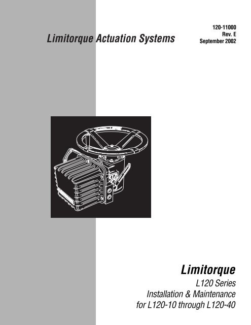
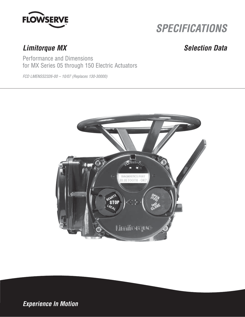
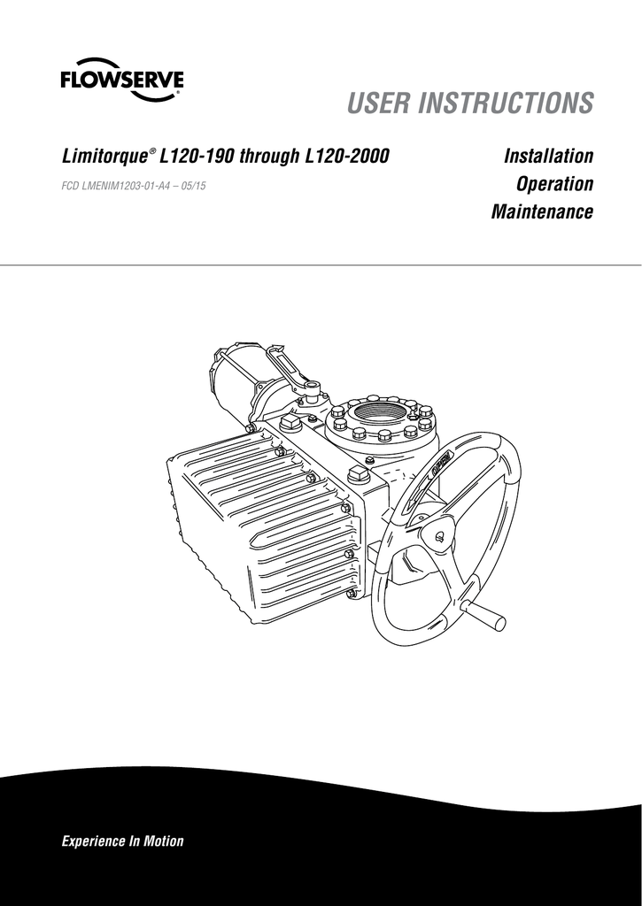
Be aware of these features and their role in the setup and operation of the actuator. Table 31 actuator weights actuator size control types drive 1 weight lbkg drive 2 weight lbkg top hw side hw top hw side hw lb.

L120 Series Electric Actuator Acrodyne
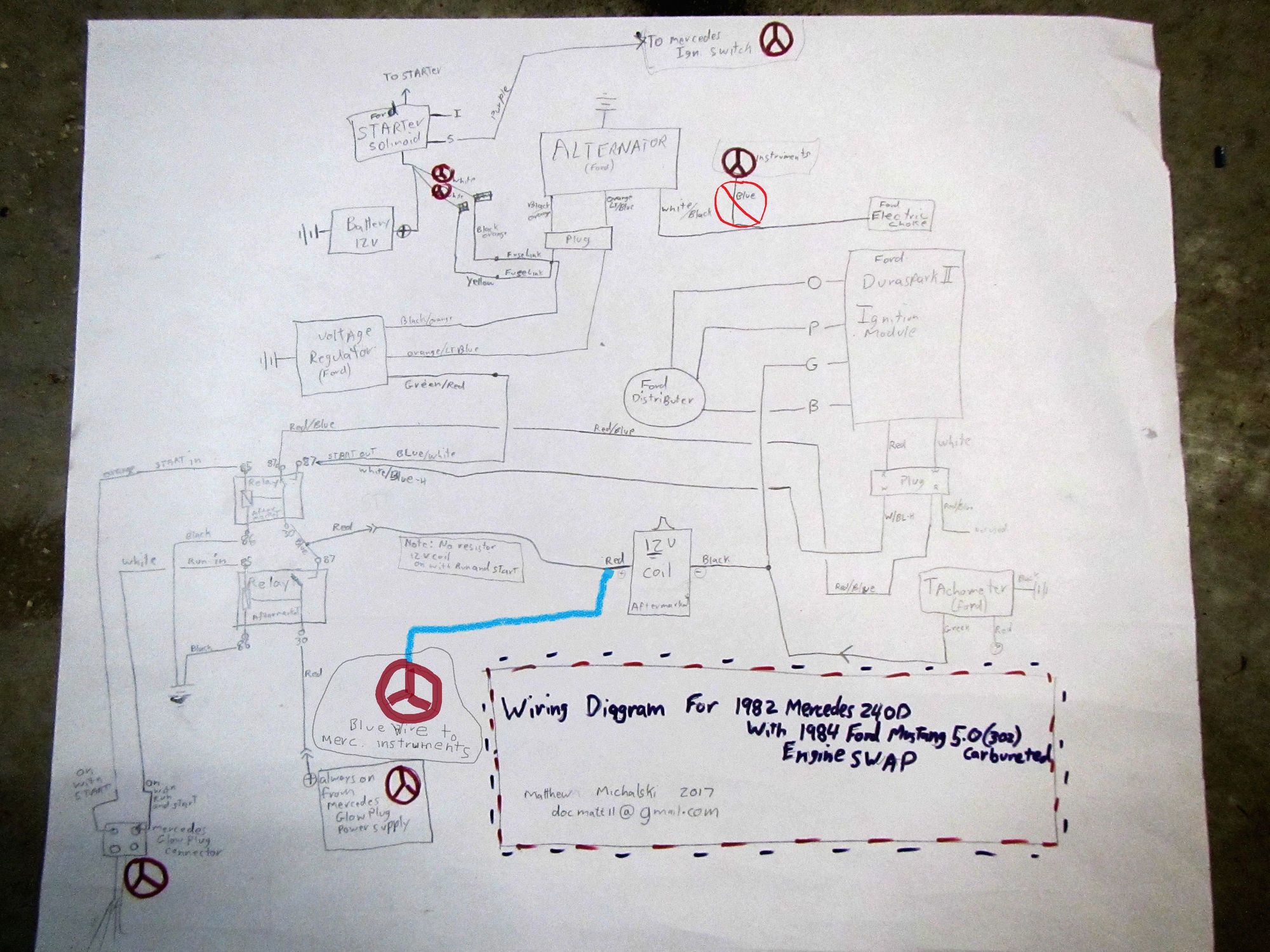
Limitorque l120 actuator wiring diagram. It shows how a electrical wires are interconnected and will also show where fixtures and components may be attached to the system. Limitorque actuation systems l120 series fcd lmenim1201 01 0706 3 actuator weights the approximate l120 actuator weights are provided below. A wiring diagram is a simple visual representation of the physical connections and physical layout of your electrical system or circuit. Whether used with gate valves globe valves penstocks or sluice gates versatile l120 series actuators operate without modification in any rising or non rising stem application for linear action valves. We have 1 flowserve limitorque l120 10 manual available for free pdf download. A wiring diagram is a simplified standard photographic representation of an electrical circuit.
It reveals the parts of the circuit as simplified forms and the power and signal connections in between the tools. Limitorque l120 wiring diagram limitorque mx wiring diagram lovely nice hf21kj005 actuator motor wiring schematic electrical. Flowserve limitorque actuators are available with a wide range of standard and optional features. Limitorque l120 wiring diagram. Consult the relevant wiring diagram for limit switch contact closed generally required if uec 3 family fig 2 development. 713 reassembling actuator sizes l120 190 420 and 800 28 714 gaskets 29 72 l120 2000 38 721 drive 2 disassembly thrust housing only 38 722 drive 1 disassembly torque housing 38 723 drive 1 torque housing reassembly 40 724 drive 2 thrust housing only reassembly 42 8 standard wiring diagrams 49 9 troubleshooting 52.
Limitorque l120 wiring diagram what is a wiring diagram. Page 22 limitorque actuation systems l120 series fcd lmenim1201 05 a4 0318 figure 51 two of two l120 10 through 40 typical wiring diagram motor reversing starter thol grnwht mtr htr note3 primary elec yelwht secondar y bluwht motor ground lug fuse sw323 pushbutton station open blured for signal. Limitorque actuators control the opening and closing of the valve and limit the torque and. 11 purpose this installation and maintenance manual explains how to install and maintain the l120 10 l120 20 and l120 40 actuators. Kg l120 10 ncu 100 45 112 51 107 49 119 54. Variety of limitorque l120 wiring diagram.
All l120 units are supplied with 8 contact limit controller is supplied switches 4 switches on each of 2 rotors. When combined with a limitorque wg or hbc series quarter turn gear. Flowserve limitorque l120 10 manuals manuals and user guides for flowserve limitorque l120 10.


