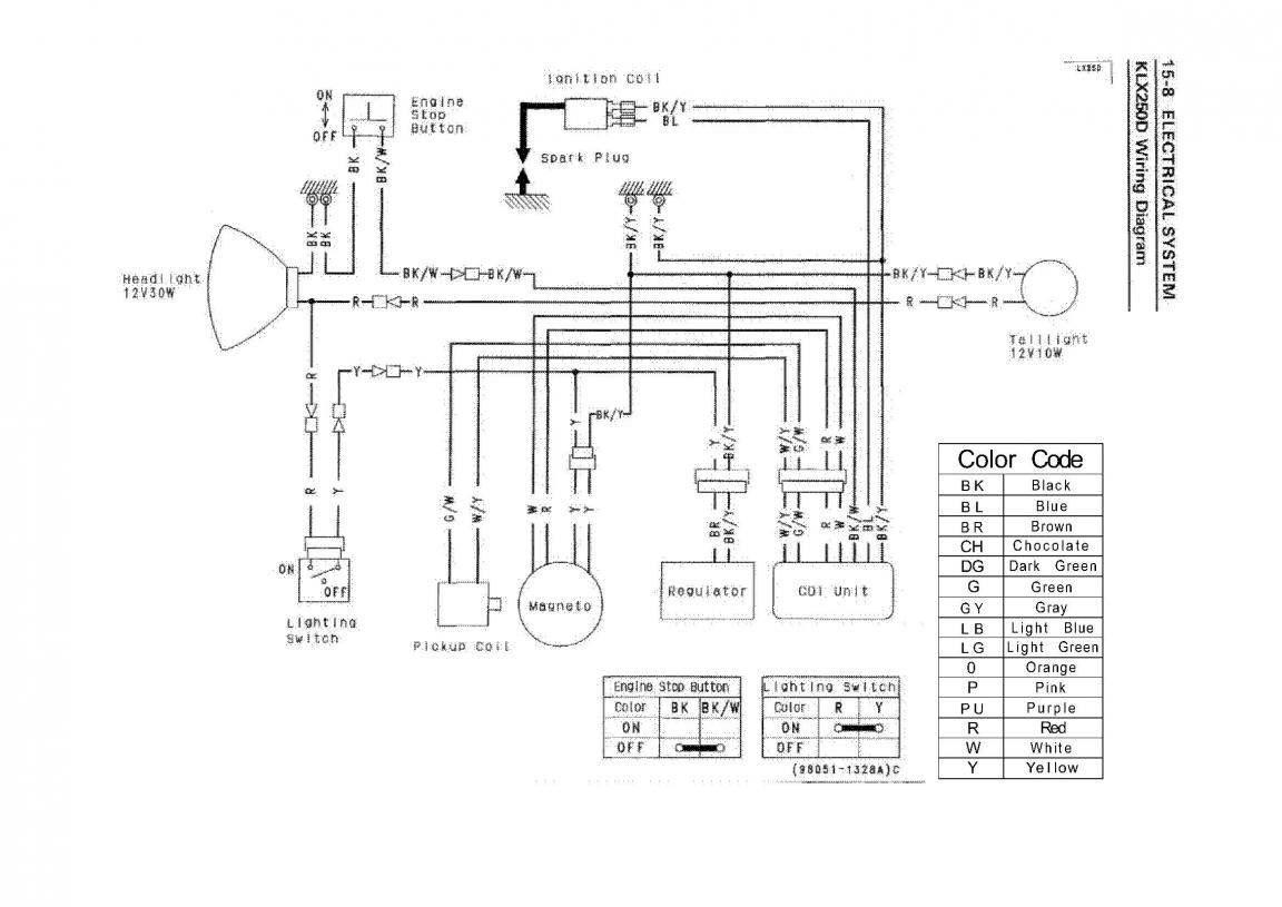
Dog chewed up wiring help lol. Tbolt usa is open and filling online orders.

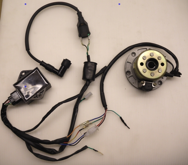
Annpee Complete Electrics Stator Coil Cdi Wiring Harness For 4 Stroke Atv Klx 50cc 70cc 110cc 125cc
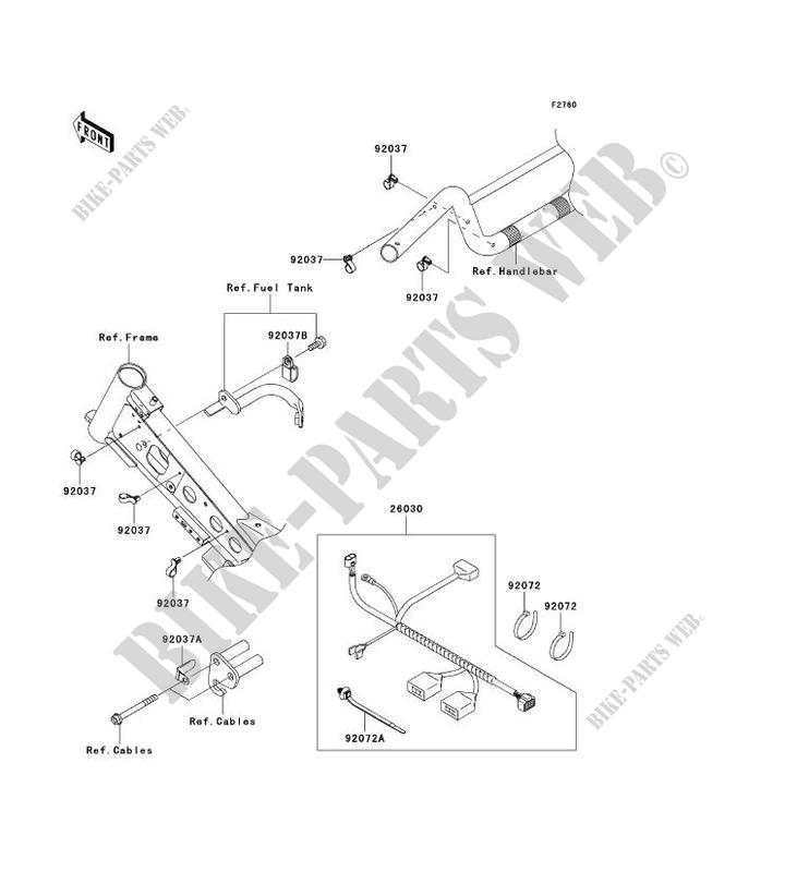
Klx 110 wiring diagram. Select a new vehicle. Air cleaner view diagram. Navigate your 2007 kawasaki klx110 klx110a schematics below to shop oem parts by detailed schematic diagrams offered for every assembly on your machine. Special tools valve seat cutter holder 45. Jump to latest follow. Brake pedal view diagram.
Check the wiring for continuity. We are not answering phones. Navigate your 2010 kawasaki klx110l klx110daf schematics below to shop oem parts by detailed schematic diagrams offered for every assembly on your machine. Starting at 2299 msrp. Motorcycle kawasaki klx 110 brochure 2010 brochure. Precautions 14 6 electrical system precautions there are a number of important precautions that need to follow.
Find diagram by part. 57001 1128 inlet special tools valve seat cutter 45 275. We are catching up but not at full speed yet. If the connector is corroded or dirty clean it carefully. Visit kawasaki motor corps usa owners center for up to date service manuals parts diagrams rok info owner support warranty info kawasaki protection plus more. For emergencies cancellations urgent issues text message 704 826 5887 some orders may be delayed a few days before shipment more info here.
57001 1330 valve seat cutter holder bar. Electrical system 14 5 wiring diagram. Use the wiring diagram to find the ends of the lead which is suspected of being a problem. If any wiring is poor replace the damaged wiring. 57001 1114 valve seat cutter 32. Offroad 2 pages motorcycle kawasaki klx 110 manual.
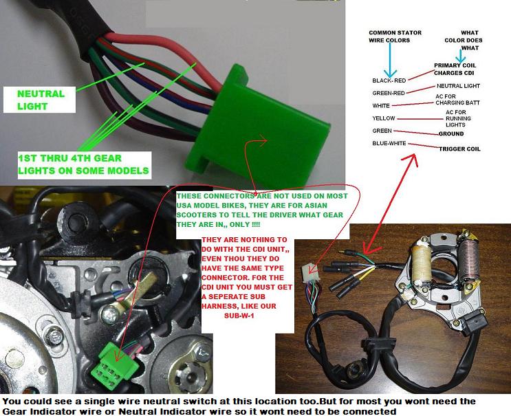
2014 klx 110 parts diagrams. Off road playbike 13 pages motorcycle kawasaki klx140 owners manual. If it is damaged replace it. Pull each connector a apart and inspect it for corrosion dirt and damage. Valve seat repair 4 26 engine top end valves valve seat repair repair the valve seat with the valve seat cutters. The gear position switch has two wires but only the light green plays the role in continuity or connection with the switch to the igniter.
The diagram that dirtbkr 188 kindly posted above confirms just that.

