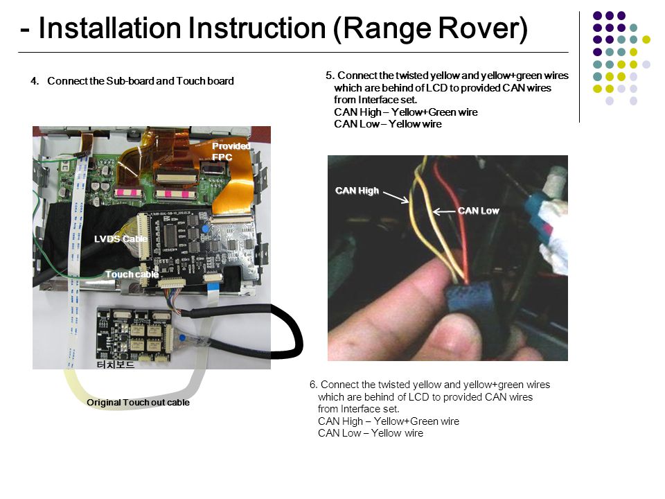
Do not use mechanical wiring connections such as crimp or snap together wire connectors. The following are diagrams courtesy of tmoss stang2birds alternator wiring diagram for 94 95 mustangs.

Aprilaire 600 Humidifier Wiring Diagram Auto Electrical
Ituran 3g wiring diagram. Output 4 on the 3g4010 must be set as active high default. This equipment has no mains onoff switch. Instead follow the instructions on pages 3 4 do not disconnect the battery if the vehicle has an anti theft coded radio or is equipped with an airbag. Whether you are a fleet operator automotivefinance institute driving your own car or a business ownerwith ituran advanced gps services youre covered. 3g4010 wiring diagrams 3g4010 wiring diagrams figure 2. 1 222 22 55 or 325 from any cellphone.
Wiring diagram book a1 15 b1 b2 16 18 b3 a2 b1 b3 15 supply voltage 16 18 l m h 2 levels b2 l1 f u 1 460 v f u 2 l2 l3 gnd h1 h3 h2 h4 f u 3 x1a f u 4 f u 5 x2a r power on optional x1 x2115 v 230 v h1 h3 h2 h4 optional connection electrostatically shielded transformer f u 6 off on m l1 l2 1 2 stop ol m start 3 start start fiber optic. Look for 12 volts at the stud on the back of the alternator where the 4 gauge power feed wire is bolted. Our gpsgprs technology based system providesinformation control at any location. The retaining clip will snap into place when the connector is properly seated. Execute full activities report about the vehicle. All wiring connections must be run in a protective conduit.
The example wiring diagram below on the right shows how this can work but also that the auxiliary supply output is an unused resource. Doing so may cause a warning light to be displayed which may require a trip to the dealer to be corrected. Car gps tracking devices installation with starter disable. With ituranyoure coveredyou will gain full control by monitoring your vehicle at all times locations. Alternator wiring diagram for 87 93 mustangs. Car gps installation is easy with online videos including car starter disable.
ˇ ˇ ˇ dl405 system ˇ ac power load supply input supply powering io circuits using separate supplies. See wiring diagram for more details. Black ground white ignition accessory 12v is supplied only when ignition is on. Connect the power cable to the vtu with the ignition off attach the power cable to the vtu.


