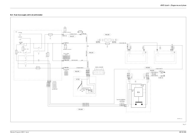
A wiring diagram is a simplified standard pictorial representation of an electrical circuit. It reveals the parts of the circuit as simplified shapes and also the power as well as signal links between the tools.

T7 185 Power Command Tractor 1 11 12 14 55
Isobus wiring diagram. Activate the 2630 isobus vt verify that the 2940 screen loads properly then refer to the operating 2940 air. Massey ferguson ih 444 te20. See marked up wiring diagram below showing how you could wire up a harness tofrom the ibbc back to a 9 pin in cab socket. Plug the virtual terminal vt lead into the isobus socket and run both wiring harnesses neatly through the tractor one needs to go into the cab for the isomatch tellus terminal while the other needs a power source which in this instance connects directly to the tractors battery terminals. This extension results in the implement and the tractor communicating over the same canbus system. The implement connector is conveniently located to attach implement wiring for implements such as seedstar planters or accudepth implements.
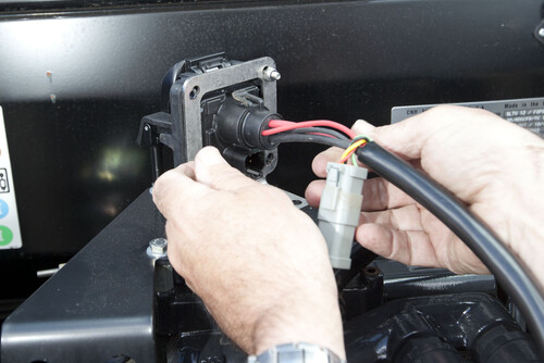
Vt gps tc implement bus tecu tractor bus. There should be two connectors one round plug cab177 on the parts diagram for the power connections and one square plug a deutsch dt connector cab180 going into the back of it tractor side. The isobus harness is now installed and ready for use. Isobus m0246 6 rev. Engine isobus plug in active terminator passive. Collection of john deere stx38 wiring schematic.
Water pump oil sump steering arm. Zip tie wiring away from pinch points rotating parts or other harmful contact with objects on the planter. Tc and isobus plug in ibbc in rear of the tractor. 14 24 april 2014 9 series air cart topcon system x30 cart harness. 516 tm system overview isobus diagram row unit pmm pcm deutschdtm04 2p p007 deutschdtm06 2s ep10 deutschdtm04 2p p007 deutschdtm06 2s ep10 a1 b2 a2 b2 a2 is gnd cc rc a1 deutsch dtm06 2s ep10 deutsch dtm06 2s ep10 hit left right w l t2 w l t1 l t lf r t implement. Isobus extends the tractor implement canbus to the implement.
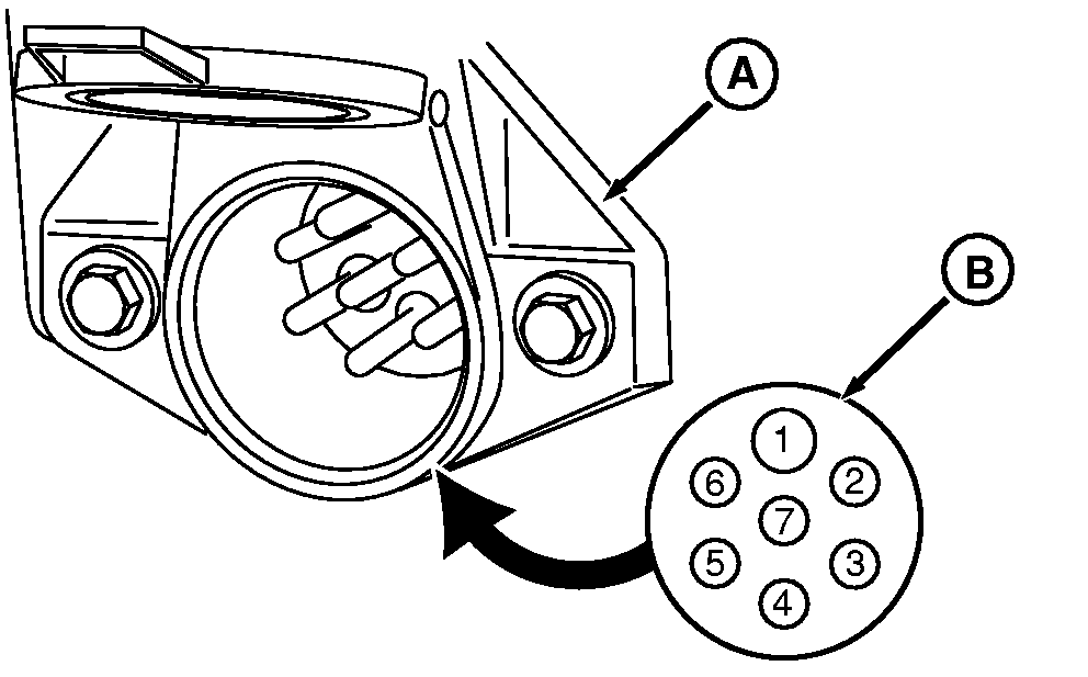
The implement connector is engineered to international organization for standardization iso standards and provides compatibility with isobus type implements. Red wire 12v to pin 4 of isobus 11783 connector or another 12v source black wire gnd to pin 2 of isobus connector or another ground yellow wire can h to pin 8 of isobus connec tor splice into circuit green wire can l to pin 9 of isobus connector splice into circuit or deere splice harness bm 08iso jd.

