Although the wiring of solenoid valve is simple but poeple still encouter problems when wiring the solenoid valve to other devices. A wiring diagram is a simplified standard photographic depiction of an electrical circuit.
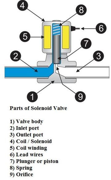
How Solenoid Valve Works Parts Of Solenoid Valves Bright
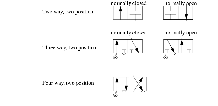
Hydraulic solenoid valve wiring diagram. Wellborn collection of hydraulic solenoid valve wiring diagram. It reveals the elements of the circuit as simplified forms as well as the power as well as signal connections between the devices. Hydraulic solenoid valve wiring diagram sample assortment of hydraulic solenoid valve wiring diagram. Composite symbol for a 4 way 2 position valve. Pushbutton pb 1 is used to activate the valve by energizing the s 1 solenoid note the valve is shown in the de energized position. August 1 2018 by larry a.
And more a wireless remote connect wire drawing also show below for single acting hydraulic power packthis wireless remote can be with a quick connector can be changed with our standard. A wiring diagram is a streamlined traditional pictorial representation of an electric circuit. Here are some details of hydraulic pump electric diagram12vdc hydraulic power unit and 24vdc hydraulic power pack hydraulic circuit diagram and electrical diagram. A wiring diagram is a simplified standard pictorial representation of an electric circuit. Assortment of solenoid valve wiring schematic. Hydraulic solenoid valve wiring diagram download assortment of hydraulic solenoid valve wiring diagram.
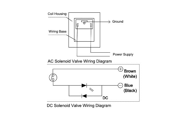
Here are some problems for your reference. It shows the components of the circuit as simplified forms and the power as well as signal links in between the gadgets. It reveals the components of the circuit as streamlined shapes as well as the power and also signal links in between the gadgets. As shown the high pressure hydraulic fluid is being routed from port 1 to port 3 and then to the bottom chamber of the piston. How to wire dc hydraulic power pack unit. The wiring diagram of the solenoid valve is as below.
Is it that the solenoid valve on the pneumatic stop valve can be two wired three wired or four wired. It shows the elements of the circuit as simplified forms and the power and also signal connections in between the tools. A wiring diagram is a simplified traditional pictorial depiction of an electrical circuit.
