800 x 600 px source. 14wire not present if hps lps dts or ctd are used.

Air Compressor Capacitor Wiring Diagram Before You Call A Ac
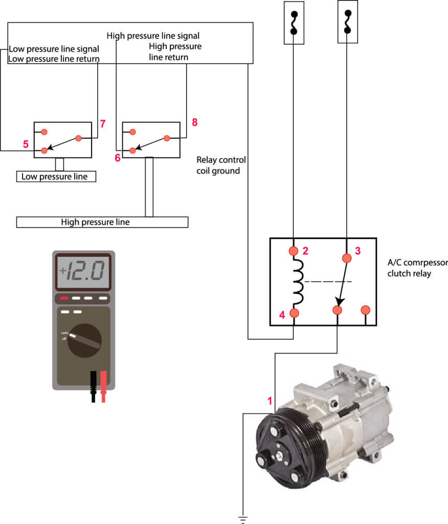
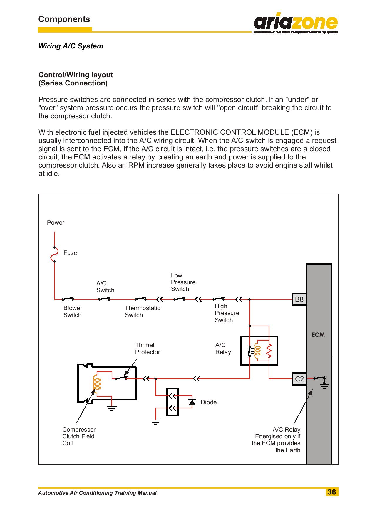
Hvac compressor wiring diagram. A wiring diagram is a streamlined standard photographic representation of an electric circuit. Factory power wiring factory control wiring field control wiring field power wiring component connection field splice junction cont contactor cap capacitor dual run 317738 401 rev. Compressor and fan motor furnished with inherent thermal protection. May be factory or field installed 320848 401 rev. How to wire an air conditioner for control 5 wires the diagram below includes the typical control wiring for a conventional central air conditioning systemfurthermore it includes a thermostat a condenser and an air handler with a heat source. 10 examples of ac compressor wiring diagram home size.
Below are a few of the leading illustrations we receive from various sources we wish these pictures will work to you and hopefully extremely relevant to exactly what you want concerning the compressor hvac pictorial diagrams is. Moreover the heat source for a basic ac system can include heat strips for electric heat or even a hot water coil inside the. 13do not rapid cycle compressor. To be wired in accordance with national. A st cap legend factory power wiring factory control wiring field control wiring field power wiring. Compressor must be off 3 minutes to allow pressures to equalize between high and low side before starting.
Variety of ac compressor wiring diagram. It reveals the elements of the circuit as simplified shapes as well as the power and signal connections in between the tools. Symbols are electrical representation only.


