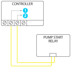
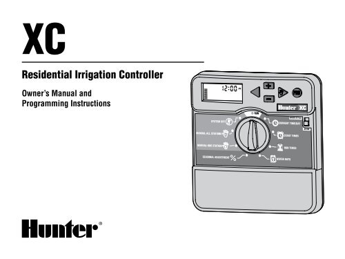
Run a single wire from the pmv terminal on the controller to the other yellow wire on the pump start relay. Different wire can be used to connect the pump start relay to the controller.

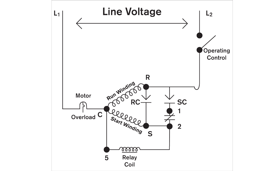
Start Relay Wiring Diagram Siosio Kasna Rmnddesign Nl
Hunter pump start relay wiring diagram. A wiring diagram typically offers details regarding the loved one setting and also arrangement of tools and also terminals on the devices to assist in structure or servicing the tool. Relay holding current draw must not exceed 028 amps 24 vac. Use wire nuts to make the connections and verify they are secure. Route a wire pair from the pump relay into the controller housing. Improper installation could result in shock or fire hazard. Install pump start relay cover plate and four screws.
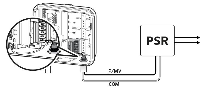
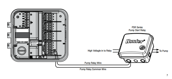
For more information on controllerpsr installation please see support page for specific controller. Power source to one side of the relay reference wiring diagram and pump start relay cover plate. Hunters pump start relay psr has been created to provide that reliabilityas well as a lockable nema rated enclosureat an economical price. It shows the elements of the circuit as simplified forms as well as the power and also signal connections between the gadgets. Connect the pump common wire to the terminal slot com common and the remaining wire from the pump relay to the pmv terminal slot. Collection of hunter pump start relay wiring diagram.
Close and lock the cabinet door. Pump start relay note. 4 check to make sure there are no exposed or loose connections. When a system requires the use of a booster pump or pulls water directly from a creek or pond its imperative to include a relay that can be counted on to activate the pump each and every time. Refer to the wire size chart below for wire size and maximum lengths. Anytime a zone is activated the pump relay is activated to pressurize the system with water.
A wiring diagram is a simplified traditional pictorial depiction of an electrical circuit. 23 431 515 a c b. Connecting the pump start relay should only be done by a licensed electrician following local codes. Available in a choice of three models to. Since the controller outputs 24volts ac power and most pumps require anywhere from 110 220 volts ac the pump relay acts as a step up transformer to route additional power to the pump and activate it. When wiring a pump relay.
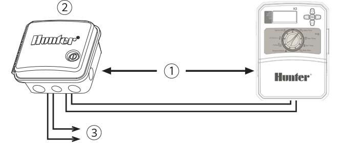
Route wire through the conduit or one of the openings on the bottom of the cabinet. This wire must be enclosed in electrical conduit and installed by a licensed electrician. Wiring the pump relay. 3 assemble conduit piping and connect wiring from the pump motor to the other side of the relay. Do not connect the controller directly to the pump damage to controller will result. Connect the wiring from the power source to the pump relay and from the pump relay to the pump.


