Collection of hayward super pump wiring diagram. Ie9 and older versions are not supported.

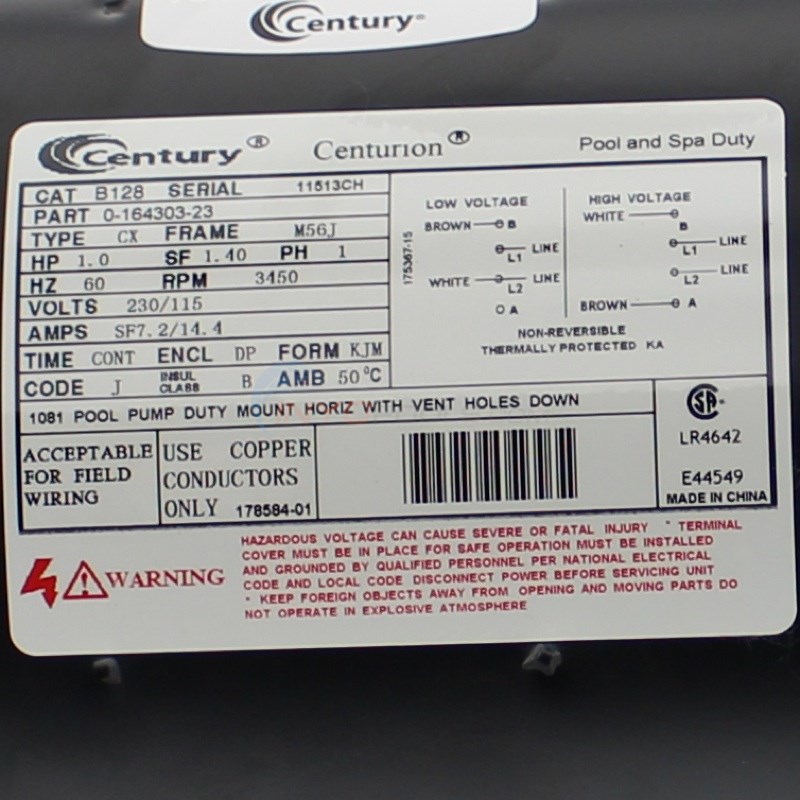
B128 Threaded Shaft 1hp 115 230v Replaces Hayward Super
Hayward super pump wiring diagram. To reduce the risk of electric shock do not use an extension cord to connect unit to electric supply. Then put you two line wires on. Hazardous voltage can shock burn and cause death or serious property damage. A wiring diagram is a streamlined traditional photographic representation of an electric circuit. All electrical wiring must be in conformance with applicable local codes regulations and the national electric code nec. December 1 2018 by larry a.
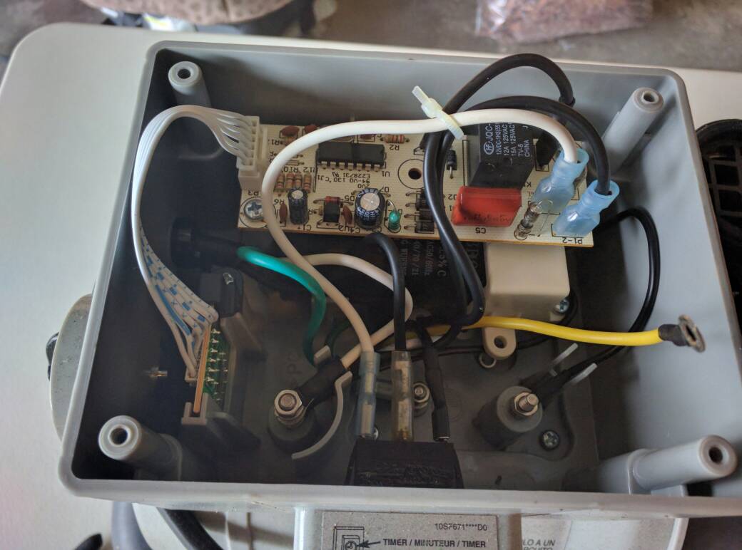
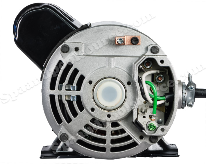
The hayward super pump. To view these documents you will need to download the free acrobat reader. It reveals the components of the circuit as streamlined shapes and also the power and signal links in between the tools. It includes directions and diagrams for different types of wiring methods and other products like lights windows etc. In this example for hayward pool pumps red will go to the l1 terminal and black will go to the if you are wiring for v the three wires to the pool pump will be black white and green. Hayward super ii pool pump wiring diagram wiring schematics diagram hayward super pump wiring diagram 230v wiring diagram includes numerous comprehensive illustrations that show the relationship of assorted items.
There should be a diagram on the inside of the wiring compartment cover if you are wiring for v the three wires to the pool pump will be. Injunction of 2 wires is usually indicated by black dot in the junction of 2 lines. According to previous the lines at a hayward super pump wiring diagram 230v represents wires. Sometimes the wires will cross. However it doesnt imply link between the cables. Variety of hayward pool pump wiring diagram.
Pumps view all products. Hayward websites have been developed in compliance with standards for internet explorer 10 or later. A wiring diagram is a simplified standard pictorial depiction of an electric circuit. It shows the elements of the circuit as simplified forms and the power and also signal connections between the tools. Follow the diagram label to connect your two v leads and your ground wire. I would wire the way it is stated on the wiring diagram.


