The bottom compartment which is segregated by a panel houses the following elements. Once downloaded you should be able to see the full file.
Openehr Architecture Overview
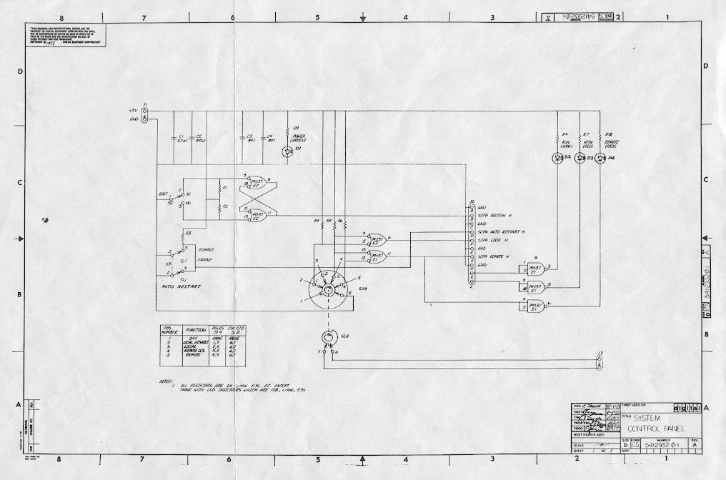
Guard evolution wiring diagram. Notes for example wiring diagrams note 1 in the wiring diagrams that are shown in this publication the type of allen bradley guardmaster device is shown as an example to illustrate the circuit principle. When the mains fail guard evolution starts the genset according to a pre set logic it switches from mainsgenset and feeds the user system. Right click and save the file to your computer. Diagram which includes an evolution indoor communicating furnace or fe fan coil with a 2 speed puron communicating outdoor unit. The guard evolution automatic device allows automated management of a mains failure. No additional oat outdoor air temperature sensor is required because the evolution control will use the temperature sensor inside the 2 speed unit.
The guard evolution device has four 4 keys allocated for standard functions and programming described below. Start key use programming this key is needed to start the engine in two different ways start normal use by briefly pressing the key the device activates the engine starting cycle after a set waiting period. Click the parts list or wiring button to begin downloading a diagram and parts list for the corresponding machine. The guard evolution device ignition key emergency stop button and optional earth fault relay device are found in the top compartment. See wiring diagram figure 13 for a typical connection diagram. Parts diagrams evolution parts wiring diagrams are available in pdf format.
Cant see the full file. When the mains come back on guard evolution switches from gensetmains and proceeds with cooling down the genset and. The amperometric transformers circuit breaker. The panel is equipped with a key lock and has a protection grade of ip54. For special applications the choice of device type is based on the suitability of its characteristics for its intended use.


