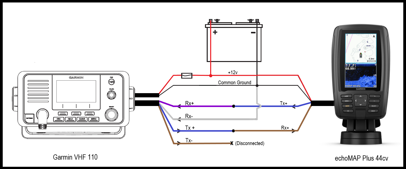
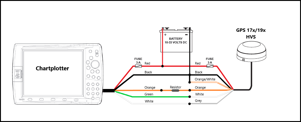
Nmea 0183 connection diagram. Garmin support center is where you will find answers to frequently asked questions and resources to help with all of your garmin products.

Working With Garmin Receivers Accessories
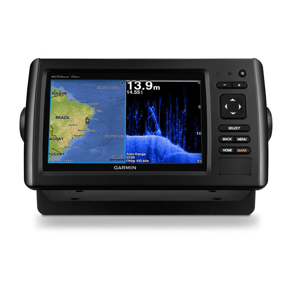
Garmin echomap dv wiring diagram. 2connect the red wire to the positive battery terminal and connect the black wire to the negative battery terminal. Owners manual reference product information user manual instructions manual installation instructions manual declaration of conformity quick start manual configuration. We have 13 garmin echomap 50s guide manuals available for free pdf download. 1route the wiring harness to the power source and to the device. Reply 1 on apr 6 2016 1221pm. 3connect the red wire to the positive terminal on the battery or fuse block and connect the black wire to the negative terminal.
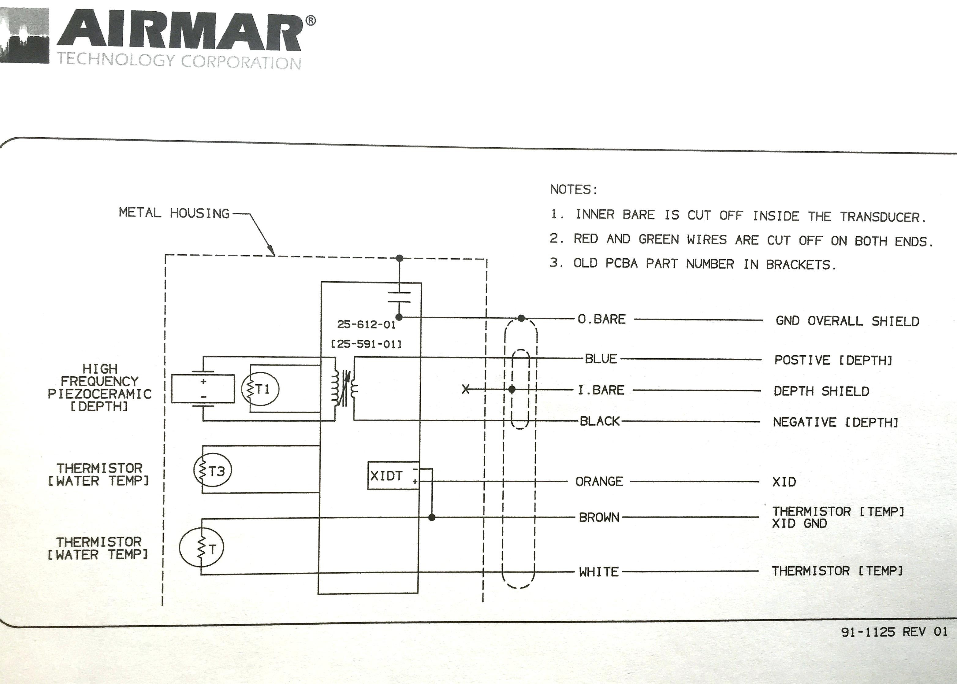
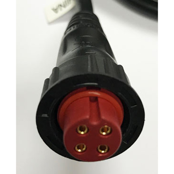
3install the locking ring and o ring on the end of the wiring harness. Play garmin marine network connector to install easily and integrate seamlessly with your compatible garmin chartplotter1. Available with trolling motor transom and thru hull mount transducer options. Wiring to power 1route the power cable from the swivel mount to the boat battery or fuse block. Solder the powerdata cable data out to the receive data rxd pin 2 of the db9 db25 pin 3 information for wiring a garmin gps to a din 8 connector is provided as a courtesy to. Connecting the device to a transducer.
Automotive oem solutions blog careers garmin express rv oem solutions shop all sales rv 890 rv navigator with a large edge to edge 8 display preloaded campgrounds and custom routing for the size and weight of your rv or towable trailer. There does not appear to be any yellow wire. 3connect the red wire to the positive terminal on the battery or fuse block and connect the black wire to the negative terminal. 4connect the wiring harness to the device by turning the locking ring clockwise. Garmin echomap 50s guide manuals manuals and user guides for garmin echomap 50s guide. Connecting the device to a transducer.
Garmin gps to pc wiring instructions introduction refer to the wiring diagram on pages which applies to your gps units type of interface connector. 2if necessary extend the wires using52 mm220 awg or larger wire. Use the transducer as a supplemental traditional and clearvü sonar source to see a historical representation of structure and fish below your boat. Wiring to power 1route the power cable from the swivel mount to the boat battery or fuse block. The brown wire is for nmea 0183 data. 2if necessary extend the wires using82 mm218 awg or larger wire.
Wiring harness nmea 0183 compliant device item garmin wire function garmin wire color nmea 0183 device wire function power red power ground black data ground txrx txrxb tx. The wiring diagram can be found in the installation manual at the following link.
