Permanent disconnection of the vehicle horn is not recommended. Box 54308 lexington ky 40505 tel.

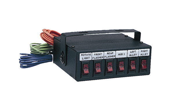
Galls 9 Function Switch Box Wiring Diagram Wiring Diagram
Galls switch box wiring diagram. Wiring your galls street thunder 6 function switch panel system before making any electrical connections determine the polarity of the vehicles electrical system ground. In addition to sirens we also carry a large selection of vehicle equipment including emergency vehicle lights switches radars speaker systems and much more. Base works with both the police and street model dodge charger can be used console box armrest internal cupholder and wiring chase view and customize mounting solutions for your galls xl switch box galls xl street thunder galls xl street thunder 6 parts list and. This input is usually wired into the vehicle horn switch. This input is usually wired into the vehicle horn switch. Auxiliary input function the auxiliary input green wire allows activation by an external source of either the horn or the manual push button functions.
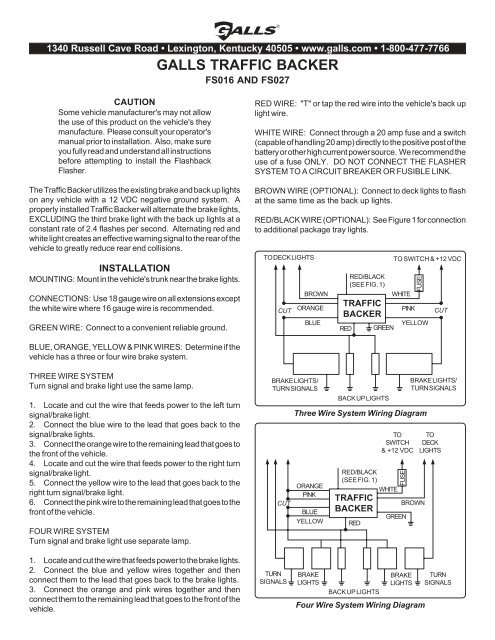
Permanent disconnection of the vehicle horn is not recommended. Connect one end of the extra red wire to the flashers red wire using a blue butt connector. The wiring diagram on page 5 shows two connection examples. Galls switch box wiring diagram wiring diagram is a simplified up to standard pictorial representation of an electrical circuit. Galls is your one stop resource for switches and so much more. Auxiliary input function the auxiliary input green wire allows activation by an external so urce of either the horn or the manual push button functions.
Galls and whelen engineering are the brands of choice for all of your vehicle equipment needs. Galls wiring diagram enthusiast diagrams galls xl wiring diagram circuit and hub galls street thunder wiring data diagrams. Permanent disconnection of the vehicle horn is not recommended. Most vehicles require the red positive wire 10 gauge to the power source and the black negative wire 10 gauge to be used as a ground wire. It shows the components of the circuit as simplified shapes and the skill and signal contacts amid the devices. Connect the small ring terminal to the flashers green wire and connect to a convenient ground.
Route the other end of the extra red wire to the control switch and cut to length. See diagram instructions below. The auxiliary input is normally activated by applying a positive voltage to the wire. The wiring diagram on page 6 shows two connection examples. The wiring diagram on page 5 shows two connection examples. Choices include five six and nine function switch boxes and a nine switch power control center.
Page 1 street thunder street thunder street thunder street thunder st280 siren amplifier light controller installation and operating instructions 1340 russell cave road po. Galls carries sirens from top brands such as code 3 federal signal star signal whelen engineering as well as our own galls brand. To activate by connecting to ground negative move the aux option jumper from the pos pins to the neg pins.


