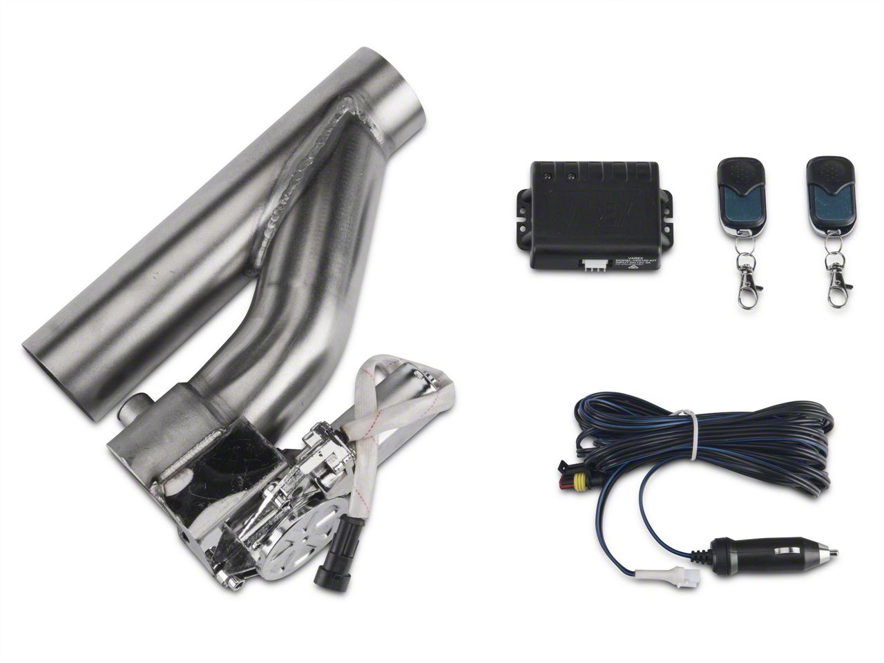
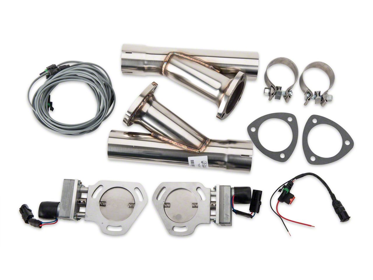
Carefully route the wiring from the cutouts up into the engine bay towards the grommet on the driver side of the firewall. There isnt much wiring that needs done.

Exhaust Cutouts
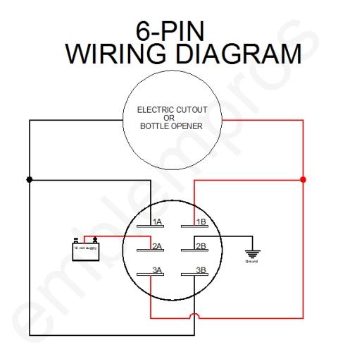
Exhaust cutout wiring diagram. Carefullymy wiring has burnt up twice now by coming loose causing the wire to touch the cat or header. Route the harness to the electric cutouts making sure to stay clear of any heat source or moving. The use of these terms is for identification and reference purposes only and does not imply that pypes performance exhaust is affiliated associated sponsored endorsed by or in any other way officially connected with the holders of these trademarks or copyrights. Connect the black wire from the switch to a chassis ground or the negative battery post. Something in the control box malfunctioned and it started melting worked for almost a year middle. The kits comes with a premade harness.
19mm 22mm billet automotive buttons wiring diagram video rgb controller duration. Electric cutout wiring diagram wiring diagram is a simplified agreeable pictorial representation of an electrical circuitit shows the components of the circuit as simplified shapes and the skill and signal friends amid the devices. I will try and explain my crude paint wiring diagram as best i can. How my exhaust cutout was wired. Exhaust cutout power windows wiring diagrams reversing polarity with relays using push buttons. The y pipe kit included with our electric cutout kit can be purchased separately in 25 inch jegs part555 30751 or 3 inch jegs part555 30752 kits to match common exhaust sizes.
Could open or close with a remote. If you need relevant productsjust clilck here. Control box gone wires straight will open the cut out. This will allow you to send the exhaust out through the valve opening giving you enhanced performance as well as great sound. Have an issue with my exhaust cutout. 3ø wiring diagrams 1ø wiring diagrams diagram er9 m 3 1 5 9 3 7 11 low speed high speed u1 v1 w1 w2 u2 v2 tk tk thermal overloads two speed stardelta motor switch m 3 0 10v 20v 415v ac 4 20ma outp uts diagram ic2 m 1 240v ac 0 10v outp ut diagram ic3 m 1 0 10v 4 20ma 240v ac outp uts these diagrams are current at the time of publication.
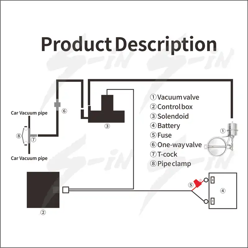
The quick time electric cutout or qtec is an electronically controlled valve that is installed prior to your vehicles muffler. A wiring diagram usually gives information nearly the relative turn and treaty of devices and terminals on the devices to help in building or servicing the. Use only a 5 amp fuse with this exhaust cutout. The pipe was installed in line with the exhaust with the exit facing outwards. Connect the green wire to a 12 volt key on ignition source such as the accessory side of the fuse block.
