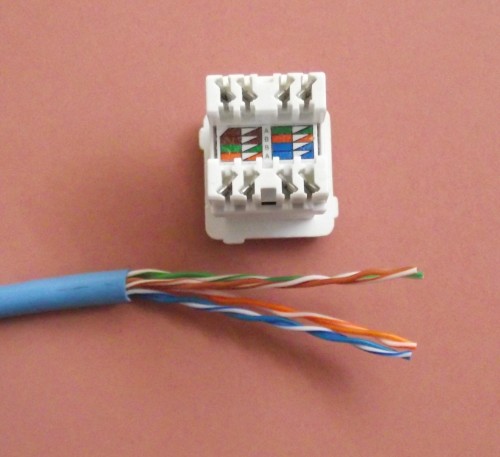
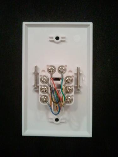
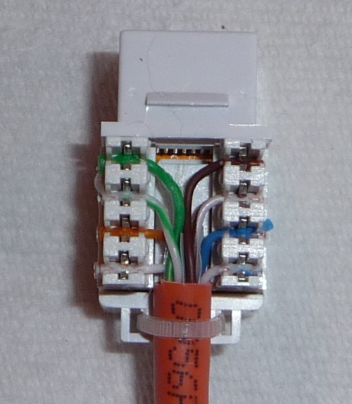
Ethernet wall socket wiring diagram ce tech ethernet wall plate wiring diagram ethernet wall jack wiring diagram ethernet wall plate wiring diagram every electrical structure is made up of various diverse pieces. For more information on how to untwist cat5.

Ce Compass Ethernet Network Cat5e Wall Plate Dual 2 Rj45
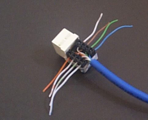
Ethernet wall plate wiring diagram. Each component should be placed and connected with other parts in particular. You can also cut out the outline for your wall plate using a drywall saw if you prefer. Collection of cat5 wall plate wiring diagram. Get amazon prime free for 30 days. Since the wall plates come in 1 2 4 and 6 jack configurations for single. Httpsamznto2jabtbi in this video i will show you how to punch down terminate an rj45 jack for a wall plate.
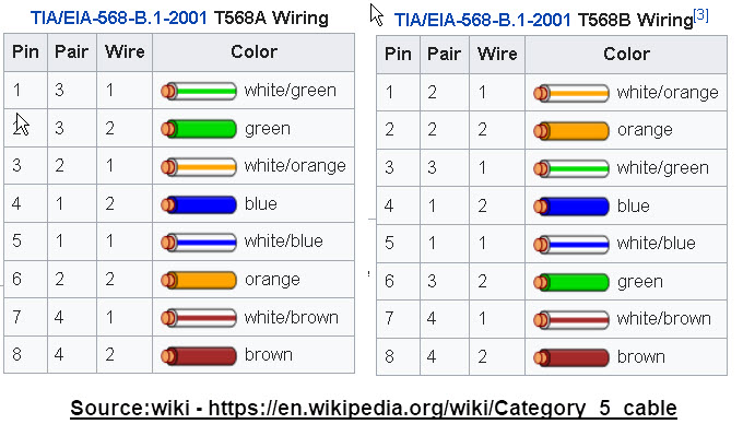
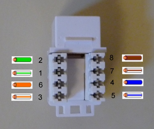
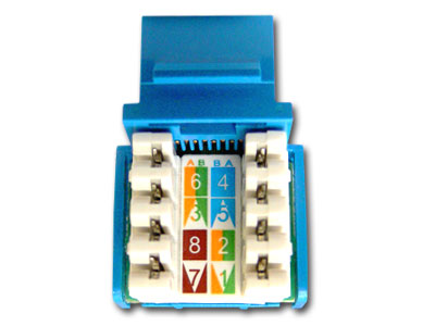
It shows the parts of the circuit as simplified forms and the power and also signal links in between the tools. Wired ethernet relies on a combination of patch cords in wall wiring and wall jacks to transmit information from the ethernet router or switch to multiple networked devices. Most patch panels and jacks have diagrams with wire color diagrams for the common t568a and t568b wiring standards. Wall socket terminates the cable in a room and accepts rj45 connectors. If not the structure wont function as it ought to be. Wall face plates these cover wall sockets.
Ethernet wall socket wiring diagram ce tech ethernet wall plate wiring diagram ethernet wall jack wiring diagram ethernet wall plate wiring diagram every electrical structure is made up of various diverse pieces. There are two standard configurations for wiring ethernet cables. A wiring diagram is a simplified standard photographic representation of an electrical circuit. Be careful not to make the hole too big. After a few passes the excess drywall will simply pop out and youll be left with a nice clean hole for your ethernet jacks wall plate. Keystone jacks these are female connectors that are usually mounted into a wall plate or patch panelthey are part of a wall socket keystone plug is the matching male connector usually attached to the end of a cable or cord.
Each component should be placed and connected with other parts in particular manner.

