On the switch the red tab is the normally closed contacts nc and the green tab is the normally open contacts no. A rheostat or dimmer makes it possible to vary the current flowing to a light fixture thereby varying the intensity of the light.

Appendix B Site Power And Power Cables
Epo switch wiring diagram. These allow the power to flow till we hit or stomp on the big red switch button then cutting the power flow. Most smart ups larger than 1500va include an epo connector for use with your epo switch. We are putting the brown active wire onto the nc contact points. The dimmer switch will have stranded wires that must be sliced to the solid cable wiring in a pigtail fashion. There should be a wiring diagram glued to the inside of the units electrical control panel however. So the epo switch will be normally open and when we push the switch in emergency time the switch normally open contacts will make a close contacts connection and the hot wire current start flowing to the coil and complete the circuit because the neutral wire current is already connect to.
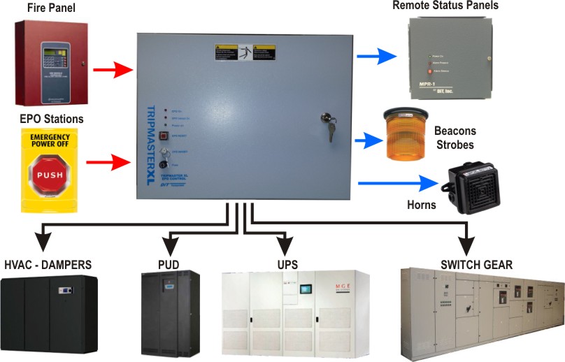
Local code may require that larger smart ups be connected to a dedicated emergency power off switch for use in an emergency. Emergency power off circuits application note an 16 app note an 16 rev. With just two wire terminals on the 24 volt side. Collection of apc epo wiring diagram. Sump pump installation diagram tripwire diagram shunt breaker wiring epo switch wiring diagramepo switch wiringshunt trip breakerplease provide a field wiriing diagram for connecting an epo in a data center to a trane model xxxxx so that the crac unit will shut down when the epo is engaged. Sua surt models feature a normally open dry contact connector.
The controls on all of these units are powered by a 24 volt transformer. Epo circuits provide a fast simple method of shutting down power to a room or piece of equipment. Dimmer switch wiring diagram. Shunt trip breaker wiring diagram with epo button. I could not find this anywhere on line. You can route the red wire attached to the 24 volt side of the transformer through your normally closed epo contacts.
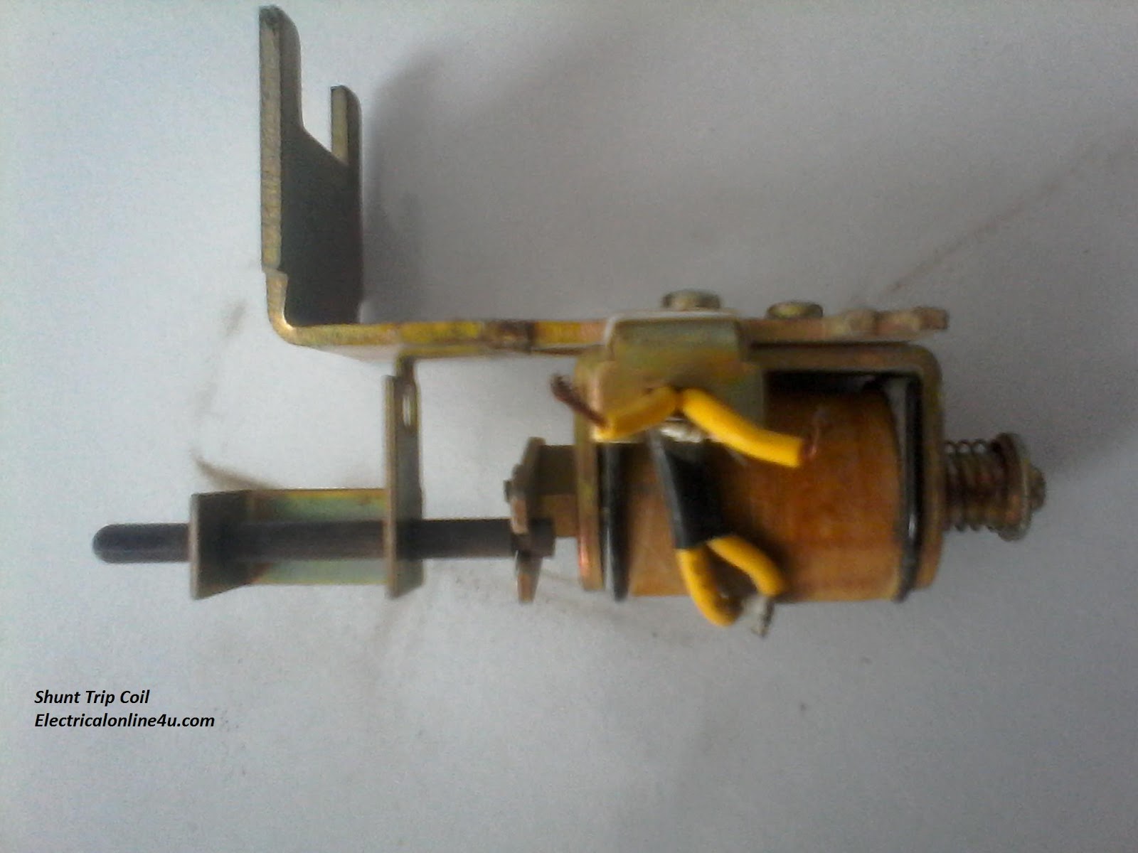
But when its come to high load places or where we use the three phase supply then use a mccb module case circuit breaker shunt trip circuit breaker with emergency push button switch which we know better with name of epo emergency power off button. Specifications electrical inputoutput voltage 24vdc 48vdc240vacexternalcircuit current 1aat24vdc 1aat48vdcexternalcircuit frequency 5060hz circuitsqty 9. A wiring diagram is a simplified conventional photographic representation of an electric circuit. It shows the parts of the circuit as streamlined shapes and also the power and signal links between the devices. A device like this should only be used with an incandescent light fixture. 20 1 1995 and 1999 teal electronics corporation the emergency power off epo button is a common feature in many medical industrial and data processing facilities.
Shunt trip breaker wiring diagram with epo button.


%2C445%2C291%2C400%2C400%2Carial%2C12%2C4%2C0%2C0%2C5_SCLZZZZZZZ_.jpg)

