Encelium extend manager wiring and installation manual pdf. Wiring diagrams greenbus ii filename kind size.
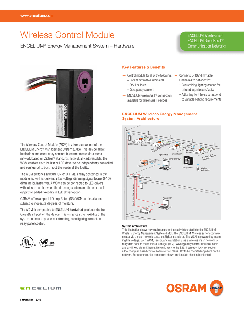
Wireless Control Module
Encelium wiring diagram. The award winning encelium extend networked light management system is a flexible and powerful way to monitor analyze and manage interior and exterior commercial lighting spaces. Search the lutron archive of wiring diagrams. Keep your diagram nearby. Encelium wireless typical riser diagram pdf. Encelium is a hybrid open to bacnet and standard light management system using a wireless mesh network based on the zigbee standard and dali digital addressable lighting interface technologies. Easily integrated into the encelium energy management system ems.
Find your product or system name. Wiring diagrams can be helpful in many ways including illustrated wire colors showing where different elements of your project go using electrical symbols and showing what wire goes where. Encelium extend system dali system specification section 26 networked lighting controls pdf. It can help reduce lighting energy consumption while providing the flexibility to adjust light levels for a wide range of tasks personal. To find a diagram for a specific product or system please use the drop down menus below. Ariadni toggler dimmer.
Specify the product or system. Each light fixture sensor and wall controller is daisy chained back to the energy control unit ecu. Refer to the product information bulletins. Encelium dali typical riser diagram pdf. Ecus typically control individual floors and are linked via an ethernet network. The example wiring diagram below on the right shows how this can work but also that the auxiliary supply output is an unused resource.
It is the only lighting control system that can gather data from a range of lighting devices to adjust lighting usage with changing building and occupancy needs and. When installing encelium wireless components safety precautions wiring diagrams and installation details shipped with each encelium lms component should be followed. Dali is a daisy chain communication topology that supply data and power to the system components. ˇ ˇ ˇ dl405 system ˇ ac power load supply input supply powering io circuits using separate supplies. Mounting diagrams eec screw hole eec screw hole to pull poe cable use nose pliers and open a hole mounting bracket j box ceiling mount wall mount 1 wall mount 2 wiring diagrams encelium edge controller encelium edge controller power supply unit ac line input poe cable sensor luminaire wclm line voltage dr signal from bms. This is why a good diagram is important for wiring your home accurately and according to electrical codes.


