Listing of emg top 10 active pickup wiring diagrams for emg 81 85 89 s sa zakk wylde bass pickups and spc exg eq circuits. Ems stinger computer system.

Diagnostic Tools Manualzz
Ems 8860 wiring diagram. Wiring harness fabrication debugging problems. Power distribution frc 12 wiring diagram. Electric guitar pickups bass guitar pickups acoustic guitar pickups and accessories emg active passive pickups over 25 years of active pickup technology the original active pickup. The ems serial race technology interface connects between an ems stinger ecu and either a data logger or a dashboard enabling monitoring of all the data channels. Ems computers pty ltd warrants the motorsport fuel injection system to be free from defects in material or workmanship for a period of two years from the date of purchase. Stinger s oftware updates.
Ems stinger 8860 6860 and 4860 ecus. Manual download for stinger. Aa spf44a spx03ea3 fb2a1 08 ag0 b a17b2 ai4 c frcj3c5 aq1 b mcsca9 f61a1 08 hb2 d a131ba4 f15a1 50 bi3 c x210aad f87 15a cust. The 8860 system provides flexible data logging capabilities to assist in gaining the maximum efficiency from an engine. 3ø wiring diagrams 1ø wiring diagrams diagram er9 m 3 1 5 9 3 7 11 low speed high speed u1 v1 w1 w2 u2 v2 tk tk thermal overloads two speed stardelta motor switch m 3 0 10v 20v 415v ac 4 20ma outp uts diagram ic2 m 1 240v ac 0 10v outp ut diagram ic3 m 1 0 10v 4 20ma 240v ac outp uts these diagrams are current at the time of publication. Manual download for 8860.
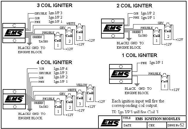
Link to ems north america. Custom harness for the ems stinger made specific for your car 350. Please choose a year from the menu at left to start your search. Ems igniter wiring nos wiring diagram 6 cylinder dfi wiring diagram 4 cylinder dfi wiring diagram 2 rotor dfi wiring diagram 3 rotor dfi wiring diagram 8. Ecu diagrams em tech series em140160180 em7080 motorsport and stinger motorsport 886068604860 stinger v4 motorsport r tech stinger s2r dualsport dualsport v6 ecus dualsport v5 ecus q and t series ecus ignition system diagrams coil ignition systems igbt ignitors sensor diagrams 4 channel egt modulelsu 49 o2 sensorspressure sensors. Welcome to winnebago industries wiring diagrams.
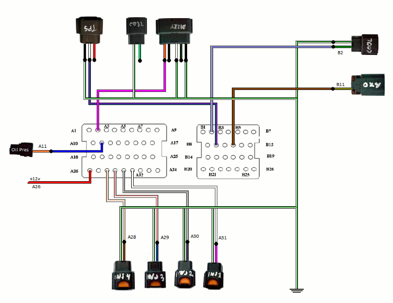
The data input rate from the ecu is set at 19200 baud which is compatible with the stinger ecu and some versions of the 8860 ecu. A b f71 15a center pin hot a b f60 30a hvac fan a b f61 5a lvd sens vendor ttu a b f76 30a 3968162 a f05 30a lecm4 b f06 20a rh sleeper pwr ports console b. 100 for map installed. Injector wiring diagram for 8860 18 injector wiring diagram for 6860 19. Proof of purchase must be provided indicating that the product is within the.


