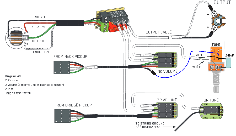
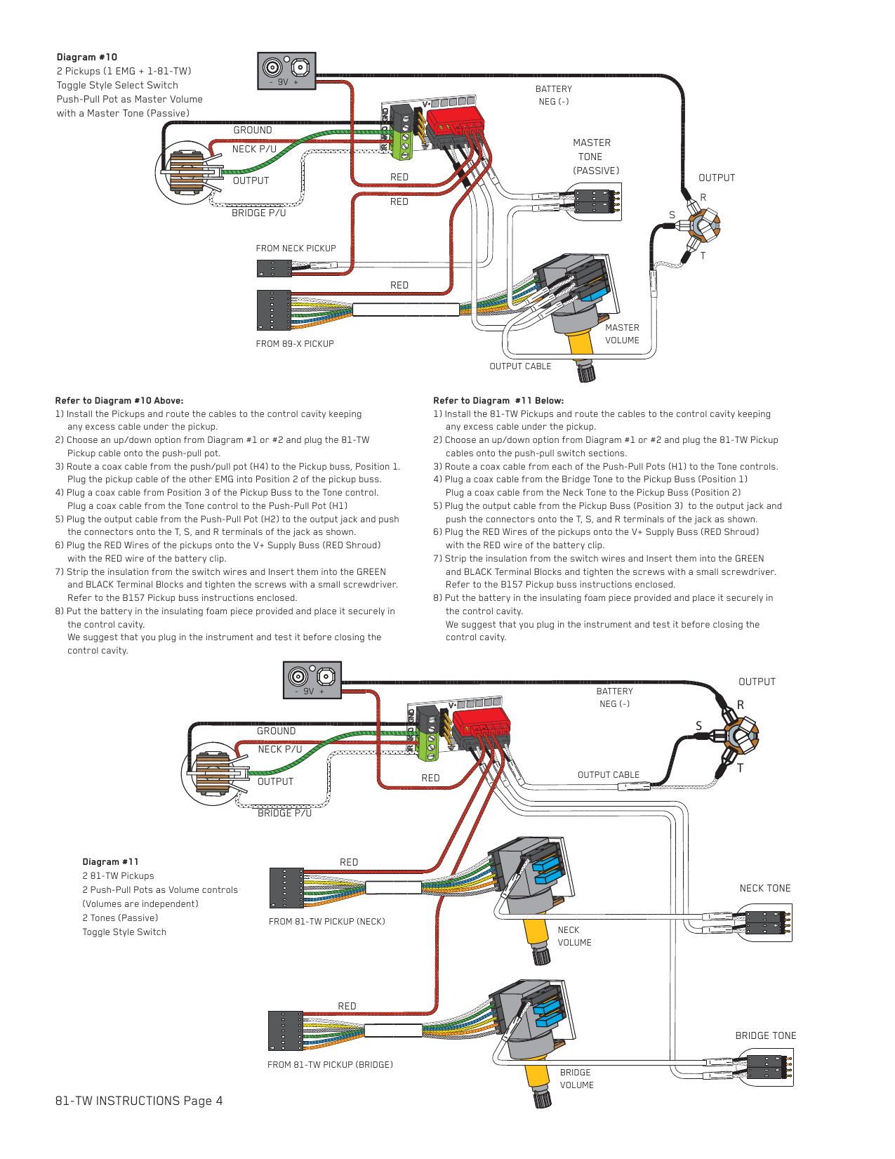
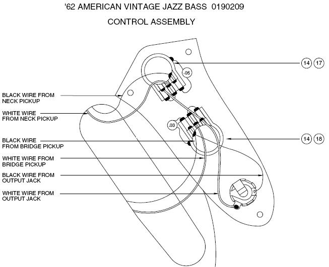
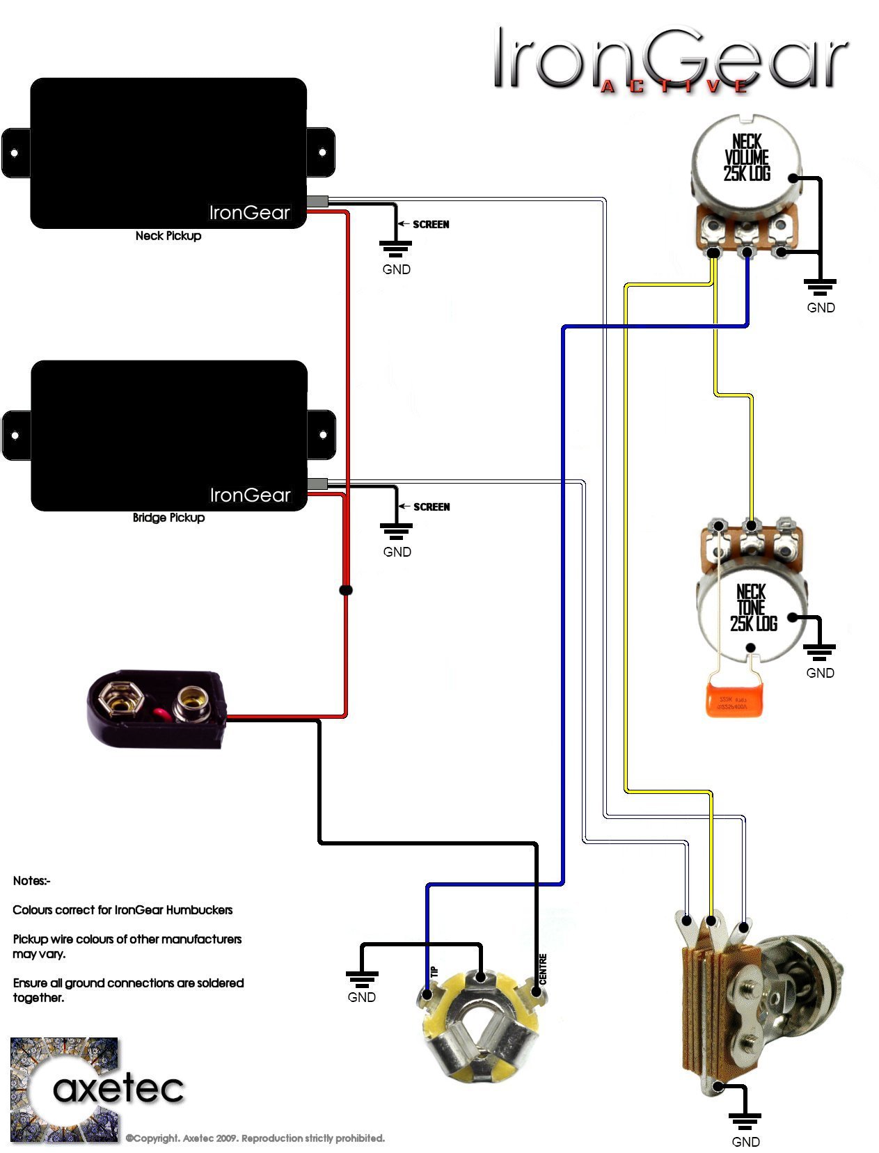
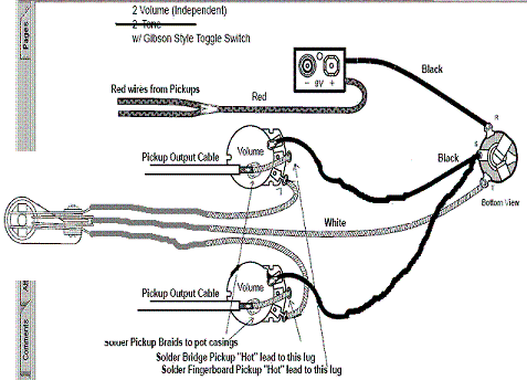
There are a variety of wiring schemes that can be employed using the 5 wire pickup cable. It shows the components of the circuit as simplified shapes and the faculty and signal contacts in the middle of the devices.

F155 Emg Wiring Diagram 81 85 3 Way Selector Switch Wiring
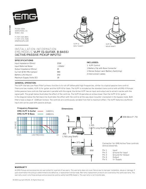
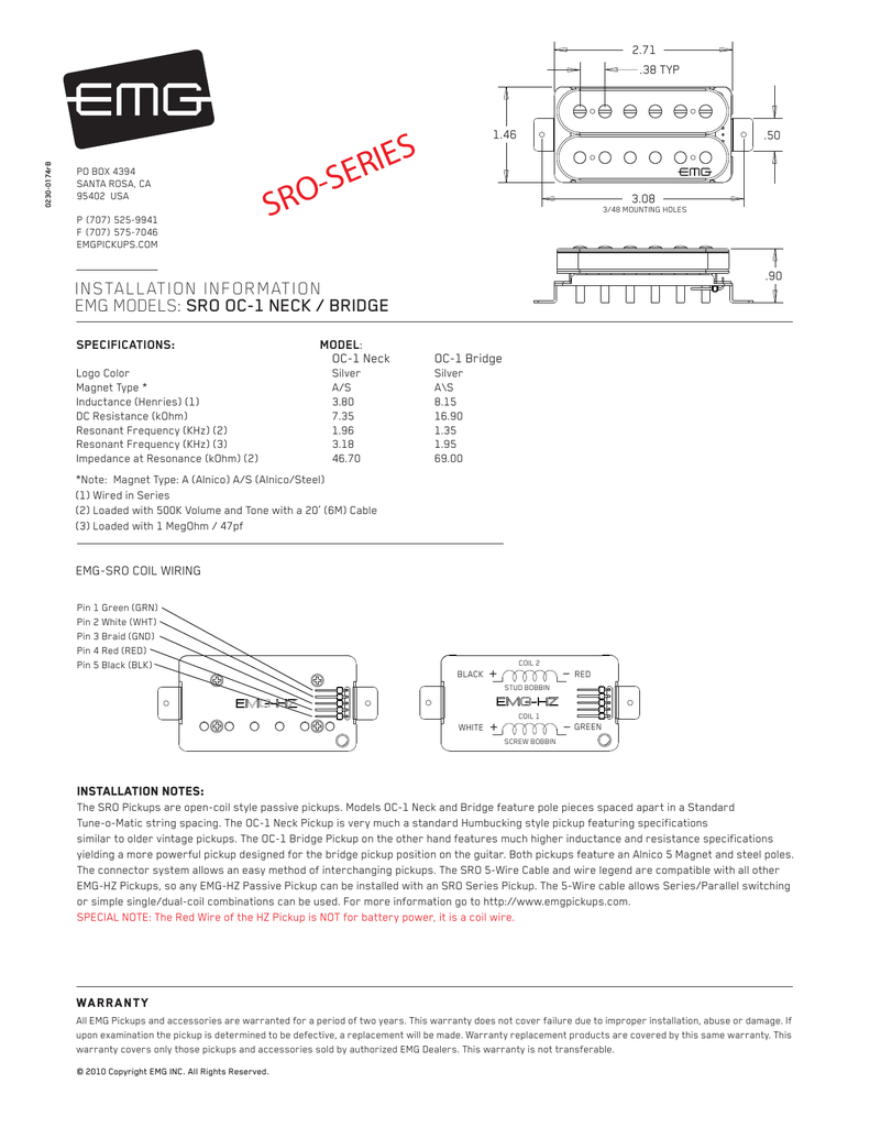
Emg hz passive wiring diagram. If the cable is too long wind up the excess and keep it under the pickup or in the control cavity if possible. So below is the wiring diagram that i use for my custom built electric guitar. I hope it can be your reference especially if you are using emg hz h4 passive pickup. Emg hz passive wiring diagram wiring diagram is a simplified okay pictorial representation of an electrical circuit. Emg pickups top 10 emg wiring diagrams electric guitar pickups bass guitar pickups acoustic guitar pickups. Emg wiring diagram emg wiring diagram emg wiring diagram 5 way switch emg wiring diagram 81 85 every electrical structure consists of various distinct pieces.
Each part ought to be placed and linked to different parts in particular manner. Emg hz pickups so any emg hz passive pickup can be installed with any other emg hz included in this data sheet are the most common wiring diagrams. The first two diagrams feature wiring for a single pickup while the rest are for guitars with 2 pickups and 2 styles of selection switch. All emg hz bass pickups feature bar style construction. Emg hz diagram 6 the legend for the coils and wire colors are shown on the bottom of the pickup. The wiring diagram for one humbucker one volume tone set up.
Electric guitar pickups bass guitar pickups acoustic guitar pickups and accessories emg active passive pickups over 25 years of active pickup technology the original active pickup. Emg hz wiring diagram. Emg tb hz instructions page 2 common wiring diagrams. If not the structure wont work as it should be. Included in this data sheet are the most common wiring diagrams. Pin 1 green grn pin 2 white wht pin 3 braid gnd pin 4 red red pin 5 black blk 1 plug the pickup cable onto the emg pickup header as shown in diagram 1 and route the cable to the control cavity.
Diagram 1 emg hz wire order.

