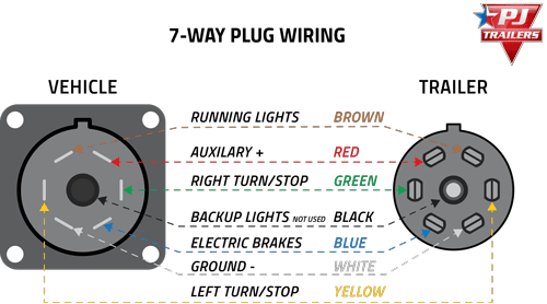
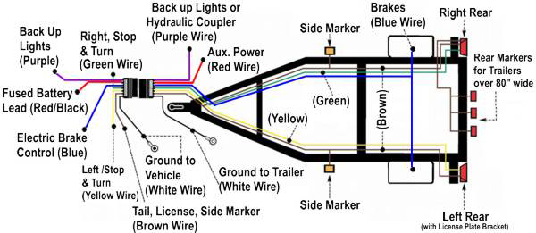
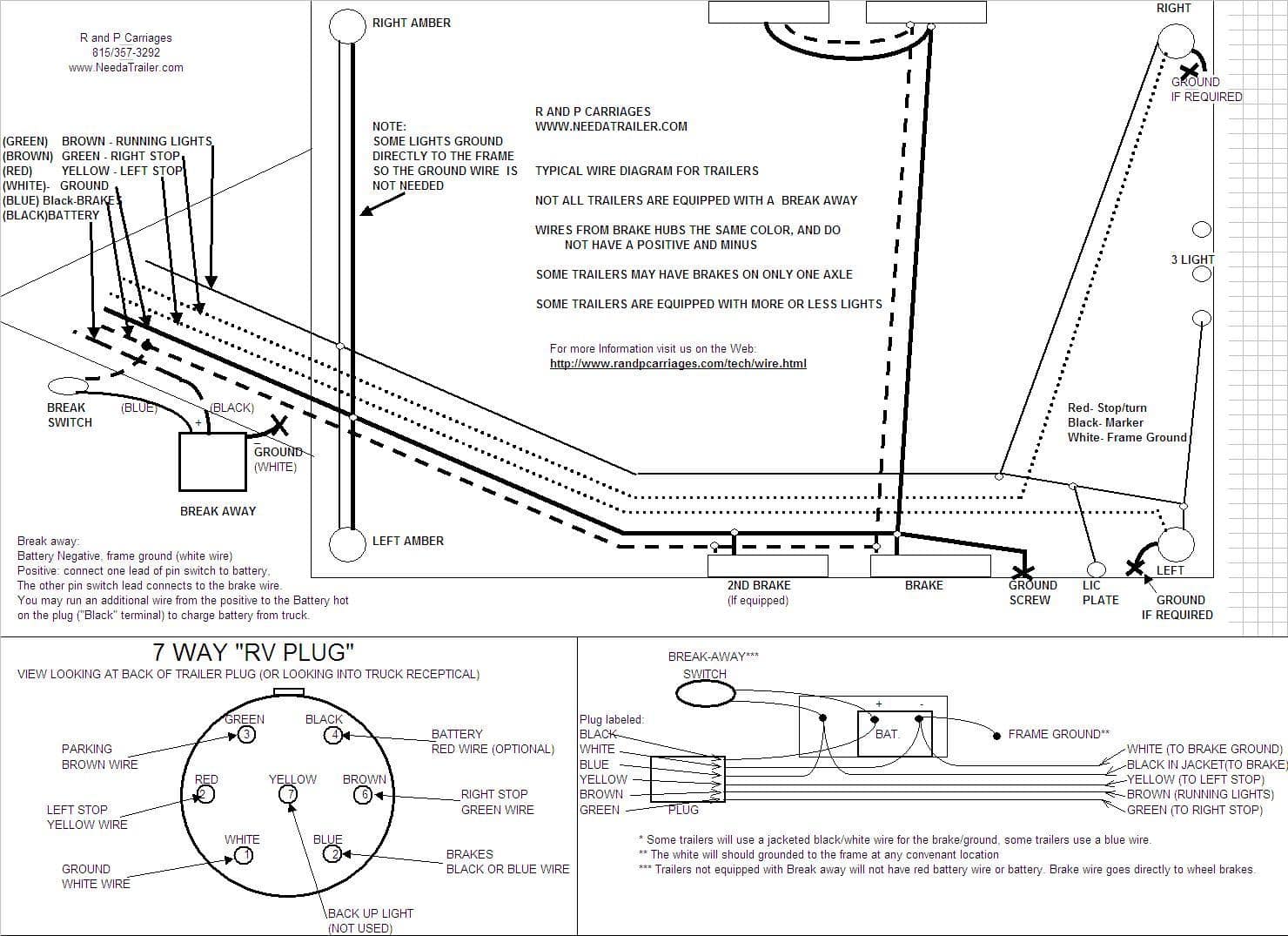
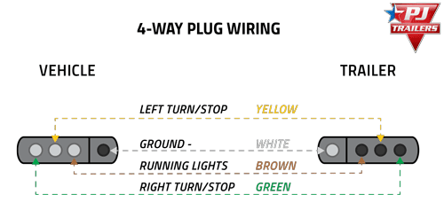
Below is the generic schematic of how the wiring goes. Collection of travel trailer wiring schematic.
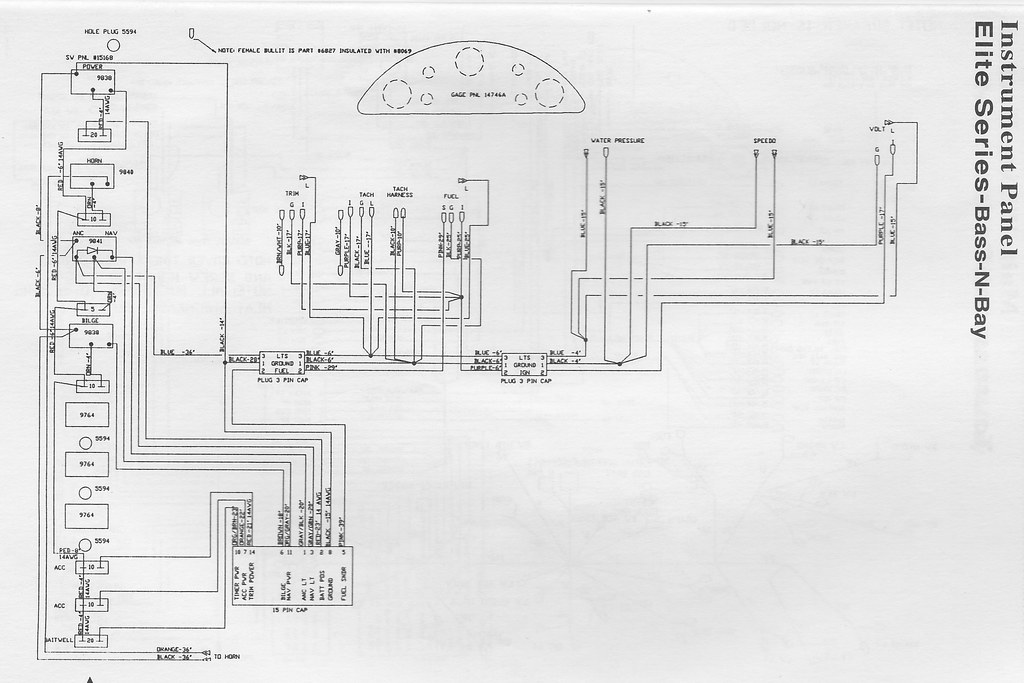
Fender Elite Wiring Diagram Harness 2015 Rmnddesign Nl
Elite trailer wiring diagram. Each part should be placed and linked to different parts in specific way. Complete with a color coded trailer wiring diagram for each plug type this guide walks through various trailer wiring installation solution including custom wiring splice in wiring and replacement wiring. Gooseneck trailer wiring diagram elite gooseneck trailer wiring diagram gooseneck brand trailer wiring diagram gooseneck stock trailer wiring diagram every electric arrangement is made up of various diverse parts. A wiring diagram is a streamlined traditional photographic depiction of an electric circuit. 4 pin trailer wiring diagram. 4 way trailer connectors are.
Many trailer sockets have a live wire to operate the electric fridge in the trailer. How to information about wiring. It may transfer electricity better so the connector is suggested for higher level electric in the vehicle. It reveals the parts of the circuit as streamlined shapes as well as the power and also signal links in between the gadgets. White pin to your ground. Different wiring options depending on the trailer and vehicle set ups.
If your vehicle is not equipped with a working trailer wiring harness there are a number of different solutions to provide the perfect fit for your specific vehicle. Trailer wiring diagrams trailer wiring connectors various connectors are available from four to seven pins that allow for the transfer of power for the lighting as well as auxiliary functions such as an electric trailer brake controller backup lights or a 12v power supply for a winch or interior. Also it must connect with things if included that use the aux power and back up lights too. Otherwise the arrangement wont work as it ought to be. Above we have describes the main types of trailer wiring diagrams. This elite trailer wiring diagram model is much more acceptable for sophisticated trailers and rvs.
They also provide a wire for a ground connection. Heres the diagram for 7 pin connector. Get a wiring diagram from the net search for trailer plug pinout or something like that you will get a very extensive list of standard wiring. Some trailer builders just connect this wire to the frame then connect the ground from all the other lights and accessories to the frame as well. The four wires control the turn signals brake lights and taillights or running lights. As the name implies they use four wires to carry out the vital lighting functions.
To connect the electric system of your trailer to the vehicle you will be using special connector. It is possible that you have a short from this live point to the light that is on or else a faulty connection. 4 way trailer connectors are typically used on small trailers such as boat snowmobile utility and other trailers that that do not use brakes. The trailer wiring diagram shows this wire going to all the lights and brakes.







/trailer-wire-colors-589d62645f9b58819cf8721f.gif)


