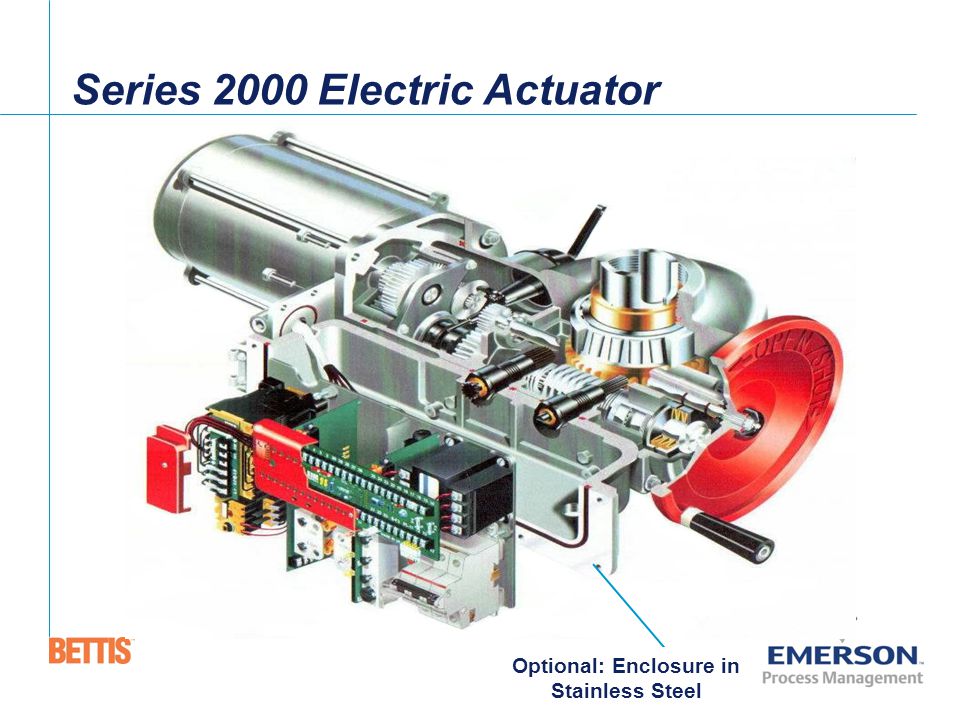
M2cp 113 model 1 author. Rely on m2cp actuators even in operating environments with severe vibration.

Ch 8636 Eim Actuator Wiring Diagram Schematic Wiring
Eim m2cp wiring diagram. Our experienced engineering and application staff is constantly developing unique and advanced safety valve solutions. Eim modular modular control package m2cp is available configured in many combinations of electrical and electronic parts. Eim furnishes a pressure relief vent fitting pn 83385. M2cp 2000 actuator iom. Figure 1 below is generic and provided primarily for wiring. Manufacturer of high quality and high performance safety relief valve products.
C at an electric power generation plant. Eim aquanaught variant of the m2cp actuators can withstand extended submersion. Eim modular control package mcp is. Refer to wiring diagram and eim job spec sheet for components provided by eim. M2cp wiring diagram symbols installation and maintenance manual september 2018 e2k 402 0817 rev. Connect control wires to tbm and power motor voltage to pwr terminals.
The digital futronic module. Installation and wiring refer to the wiring diagram supplied with the actuator for wiring details and options supplied with the system. The control module uses eims m2cp tbm01 termination panel for interface of all analog control types. Placement on actuator can be determined only after field location and position of valve has been determined. Eim m2cp actuator manuals. Page 22 section 6.
Refer to wiring diagram and eim jobm2cpkbg bevel gear actuator in high temperature steam service 1f. Select the highest 12 npt vent location in the gear box remove 12 npt plug and replace with pn 83385. 3 figure 25 reversing contactor showing open and close coils mechanical interlock and electrical interlock contacts o 21 22 c 21 22 figure 26 nuisance trip to prevent tso contact tripping when valve has been jammed. Possible locations of the plugs are shown on eim outline drawing.


