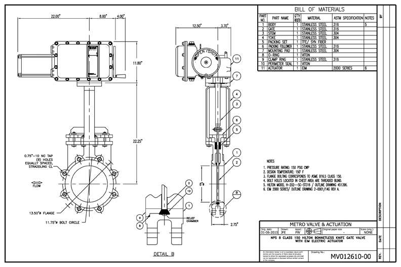
Liquid analysis wiring diagram. Eim 2000 series e796 m2cp.

40a3 Ecu Wiring Diagram In Pdf Wiring Resources
Eim 2000 series actuator wiring diagram. Eim actuators are factory filled with a high quality lubricant carefully selected to insure. The four most common frame sizes of eim actuators the 1000 2000 3000 and 4000 establish the foundation for the 2000hp. 1 august 2017 maintenance at least once a year a check should be made of your eim actuator. 2102 locknut lockpin installation 1. Storage instructions e2k 401 0817 rev. Limit switch setting instructions e2k 402 0817 rev.
Eim 2000 series e1195 mcp product discontinued i installation and maintenance manual. Refer to wiring diagram and bettis job spec sheet provided by bettis with each actuator. 3 september 2018 section 4. Either incoming power or motor wiring must be reversed. M2cp was 2000 series. 20 recent auma electric actuator wiring diagram.
0 july 2018 eim series 2000 aquanaught operate submerged actuators. I installation and maintenance manual e2 402 0817 rev. I user manual 84829 ev d table of contents march 2013 tabl ontents. With the actuator in place on the valve ensure proper flange mating and valve. Eim 2000 aquanaught series controller pdf manual download. View online or download emerson eim 2000 series installation and maintenance manual operation and maintenance manual.
M2cp wiring diagram symbols. Operate submerged actuators confidently. Emerson eim 2000 series pdf user manuals. Eim actuator wiring diagram sample 20 recent auma electric actuator wiring diagram. Eim 2000 series m2cp digital futronic. Limit switch setting instructions before making limit switch setting move.
Adapter must engage a minimum of one screw diameter deep into eim actuator base. 2 table of contents. The 2000hp is based on the proven eim series 2000 platform and shares many of its distinctive features and benefits such as direct mounting and handwheel operation during power loss or emergency situations. Eims actuators have definitely improved the electric actuator reliability decreased downtime and improved productivity in our coker units. Refer to the wiring diagram supplied with the actuator for wiring details and options supplied with the system. Rotork wiring diagram rotork wiring diagram 8000 dolgularsc 1.
Lennox furnace wiring diagram. 0 july 2018 figure 10 wiring diagram. Electronics setup operation and maintenance manual e2k 200 0718 rev. It fits broad range of quarter turn and multi turn applications. Limit switch setting instructions installation and maintenance manual section 4. Maintenance installation and maintenance manual section 1.
If valve goes wrong direction when button is pushed you have no torque or limit protection. Page 1 operation and maintenance manual e2k 200 0718 rev. Figure 1 below is generic and provided primarily for wiring.


