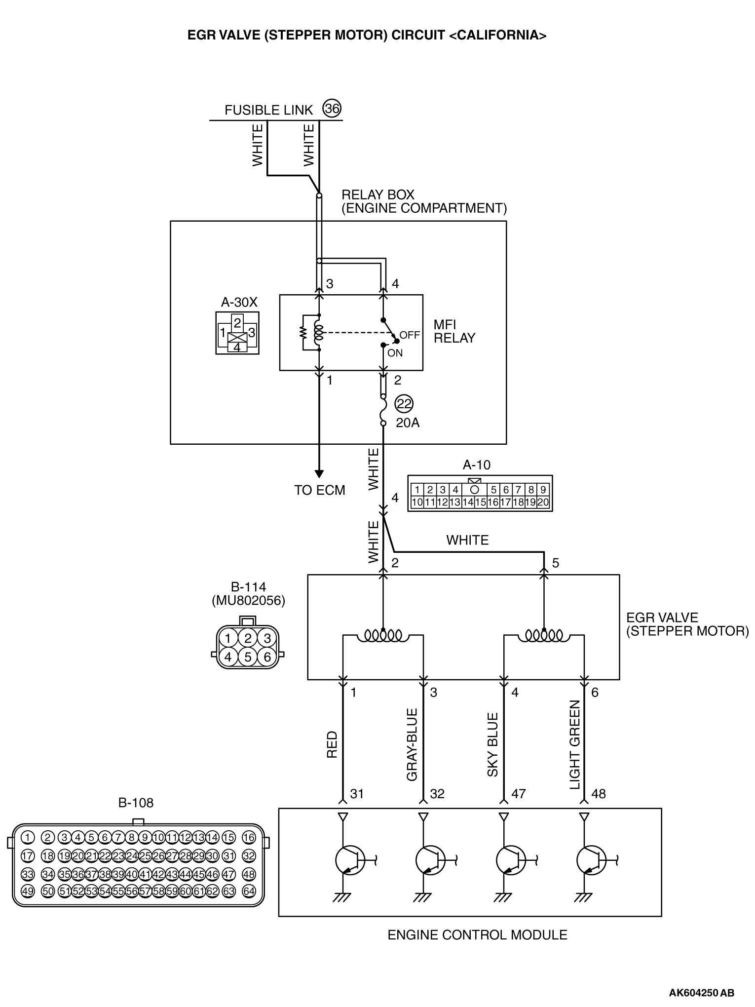
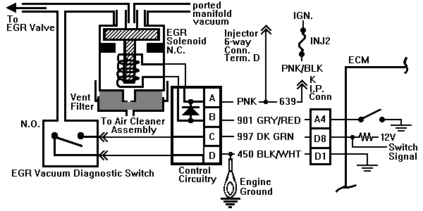
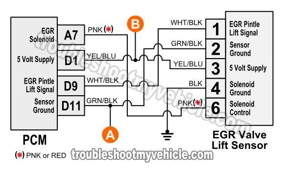
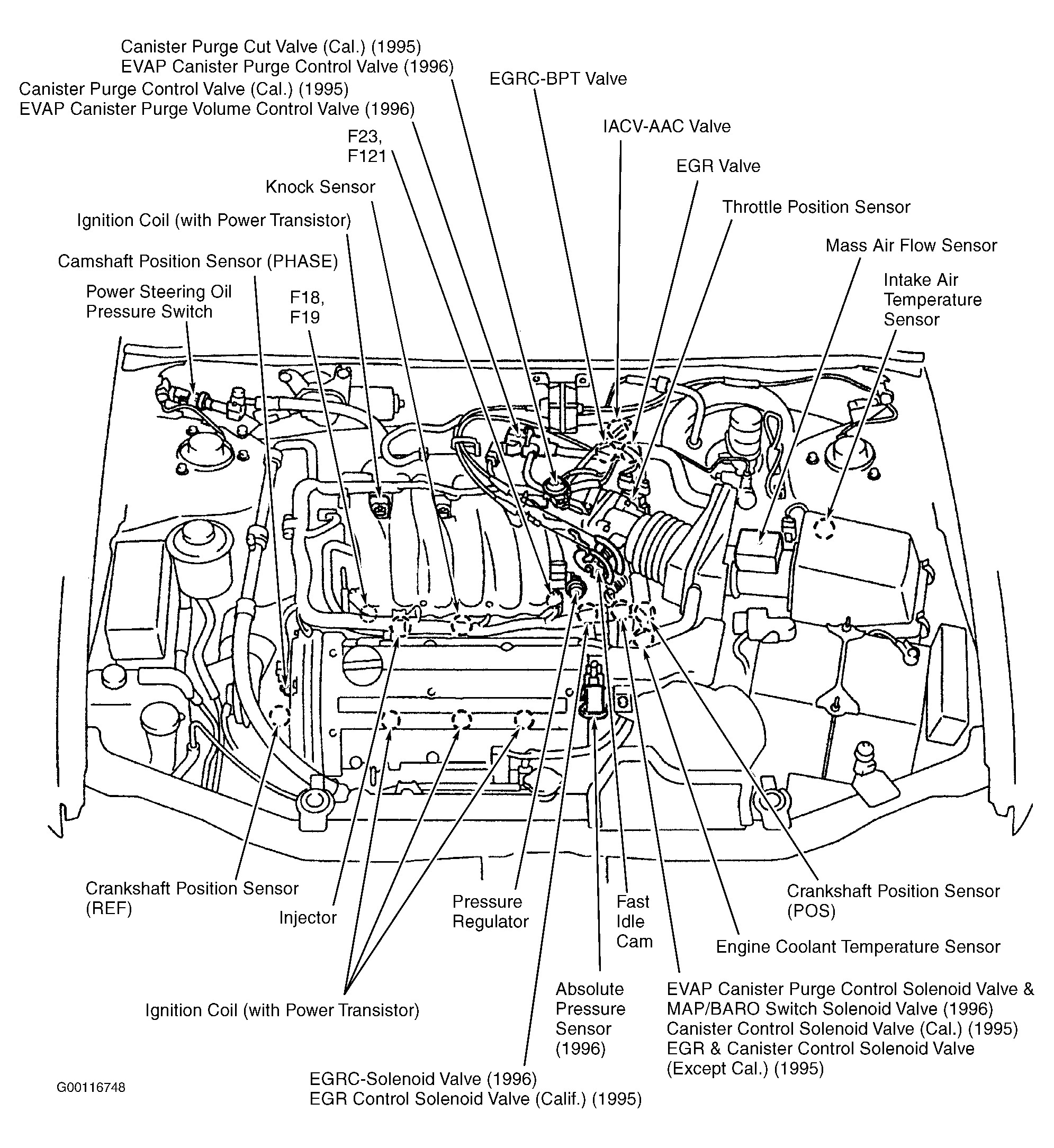
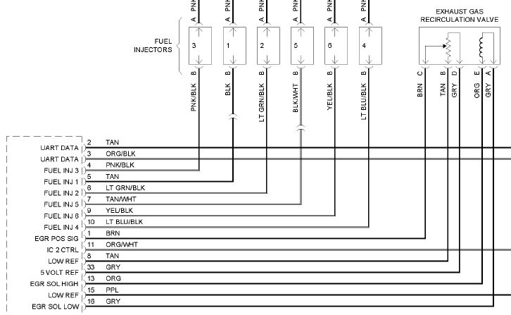
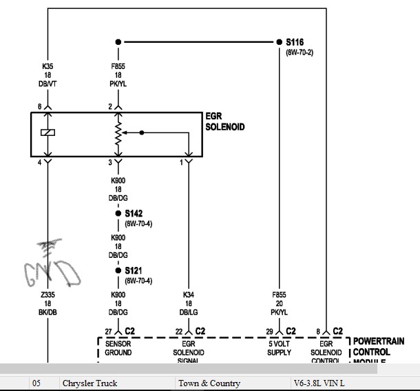
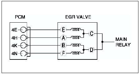
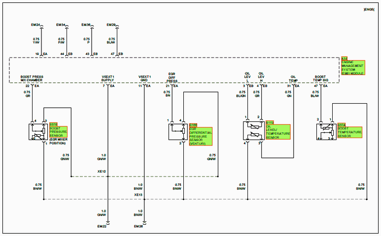
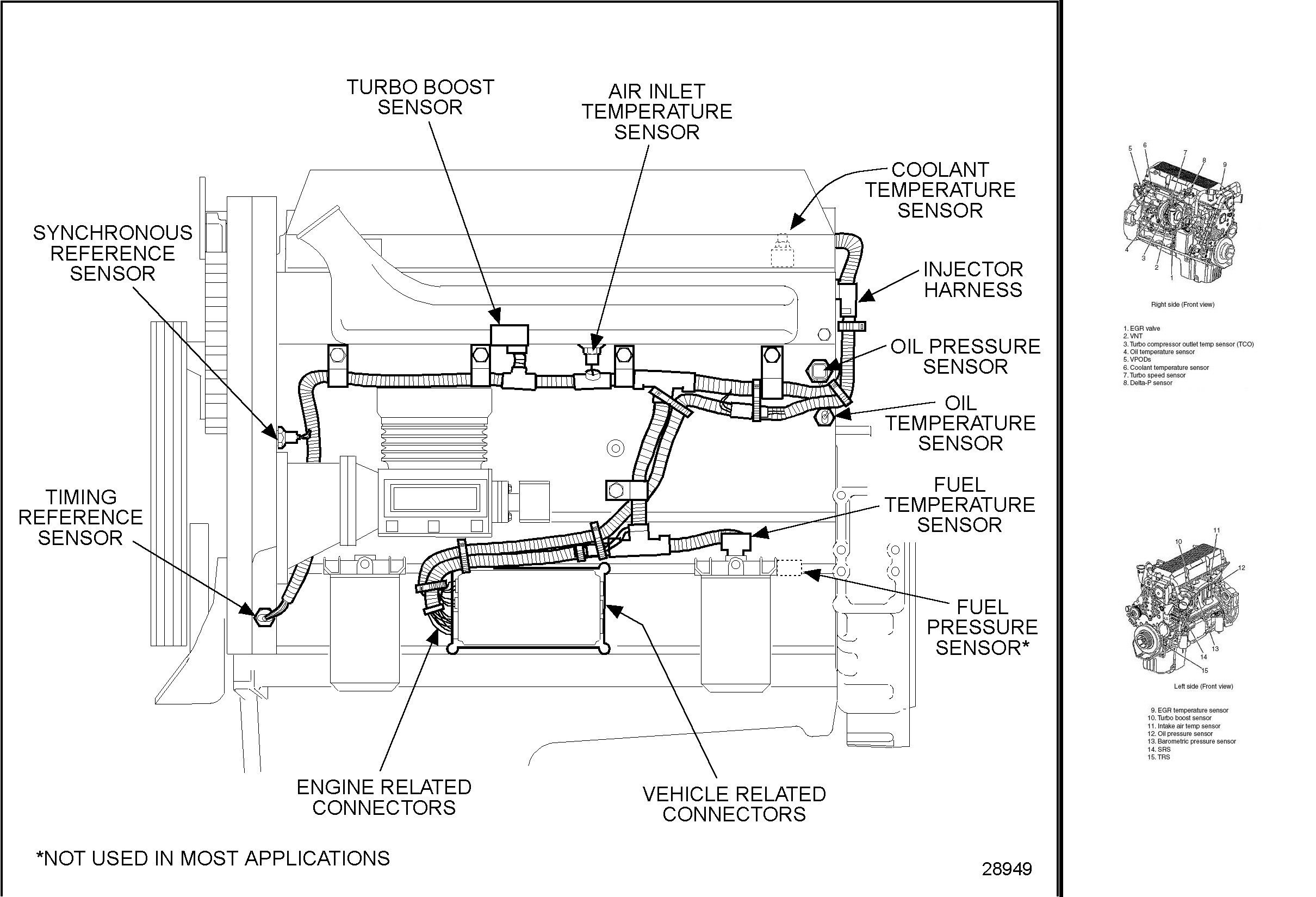
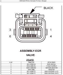
It demonstrates how the electrical cords are adjoined and also can also reveal where fixtures and parts could be attached to the system. Signs that represent the elements in the circuit as well as lines that stand for the links in between them.
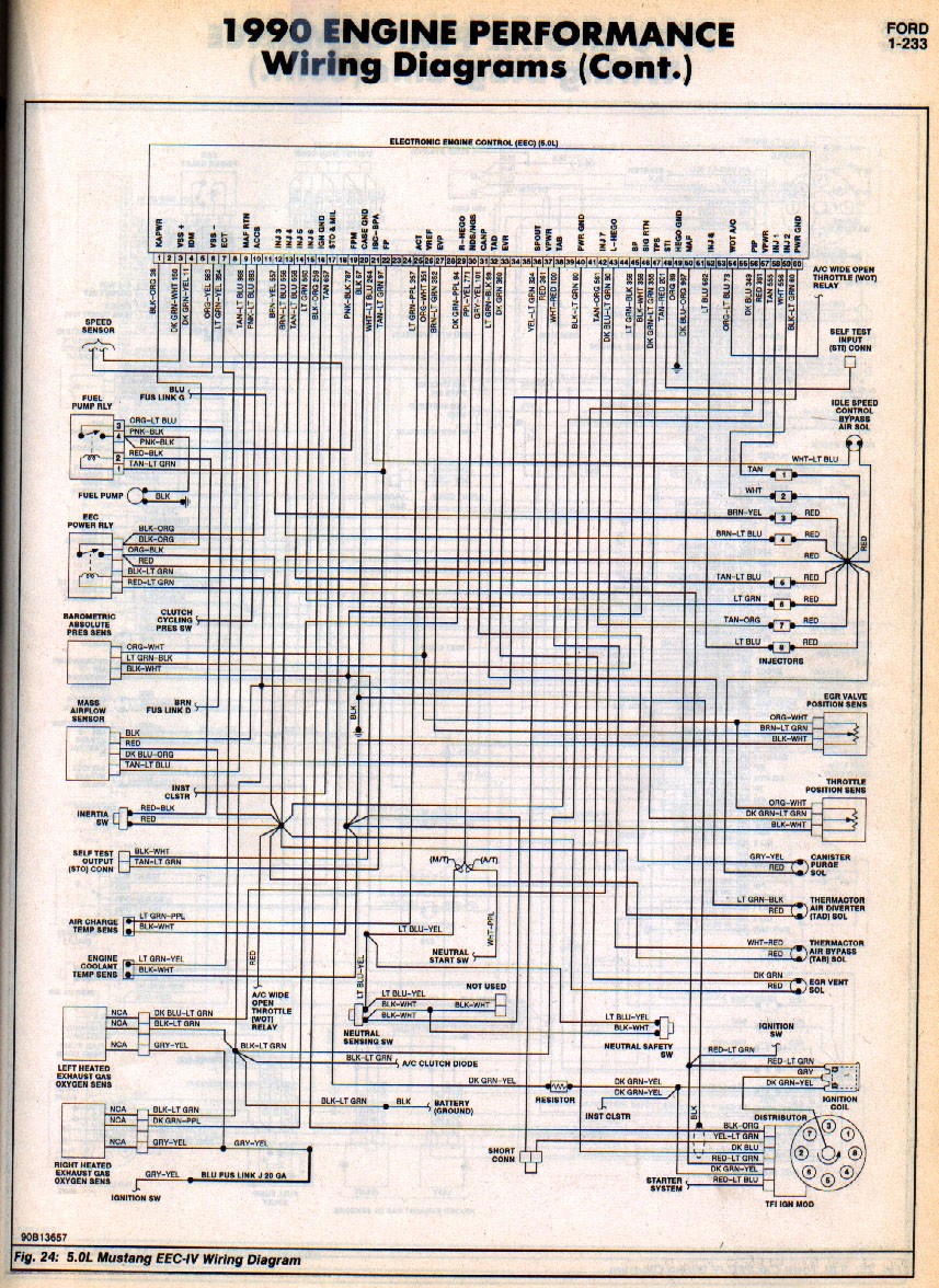
64a8 2003 Ford F 150 Egr Sensor Wiring Wiring Resources
Egr wiring diagram. When faults occur it is due to the valve sticking partially open or binding so the ecu signal is no longer able to open it. Cummins isx egr wiring diagram wiring diagram is a simplified pleasing pictorial representation of an electrical circuit. It shows the components of the circuit as simplified shapes and the faculty and signal contacts between the devices. If a component is most likely found in a par ticular group it will be shown complete all wires connectors and pins within that group. When as well as exactly how to use a wiring diagram. Wiring diagrams component locations torque specifications fluid types and capacities and maintenance schedules.
Damage to wiring or connectors problems with pressure hoses or the dpf pressure sensor issues with regeneration of the dpf and a bad egr valve or its circuit. The wiring diagrams are grouped into individual sections. For exam ple the auto shutdown relay is most likely to be found in group 30 so it is shown there complete. Ad g g02 alternator b r b i xg9 stud engine block battery g01 battery x2a180 spx2a x2a550 spx2a5 spx1e x2a250 spx2a2 x2a708 gdo2 b a833 x3a330 x2a350 spx2a3 x1m80 gg2 c x31a1a x2a820 nao2 b hookuplpb x2c1 x2a130 x1e80 x2d 130 x3a920 x2a1020 nao3 b spign1b x1 stud cab ground 1 1 spx2a4. The ford dpfe and egr systems are unique and you must understand how they work if you want to diagnose and fix them. Plus they contain full trouble code descriptions and troubleshooting instructions.
Egr valves are commonly a simple two wire solenoid valve driven open by a pulsed ecu signal and returned closed by spring pressure. Electrical wiring representations are made up of 2 things. A wiring diagram is a simple aesthetic depiction of the physical links and also physical design of an electrical system or circuit. A wiring diagram is a type of schematic which utilizes abstract pictorial signs to show all the affiliations of components in a system.
