Dx 9100 extended digital plant controller including dx 912x lonworks version 3 3 introduction 3 features 8 installation 11 version 1 dx 9100 8154 11 version 2 dx 9100 8454 or fa dx9100 8454 and version 3 dx 912x 8454 19 general wiring guidelines 34 battery replacement 35 startup 38 inputsoutputs 39 analog inputs 39. The display can act as a simple adjust and indication unit or be used for more complex tasks often associated with a workstation.
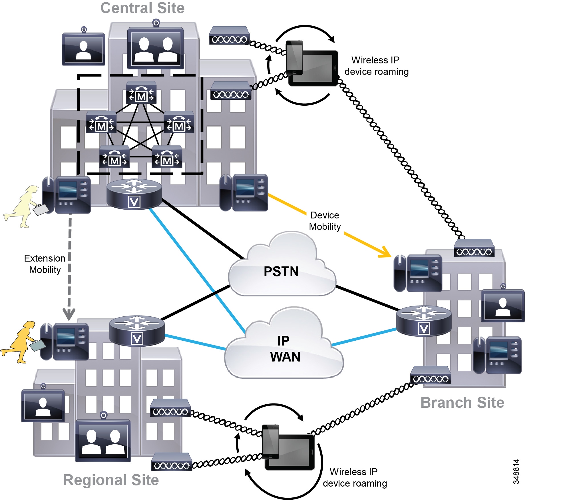
Cisco Collaboration System 11 X Solution Reference Network
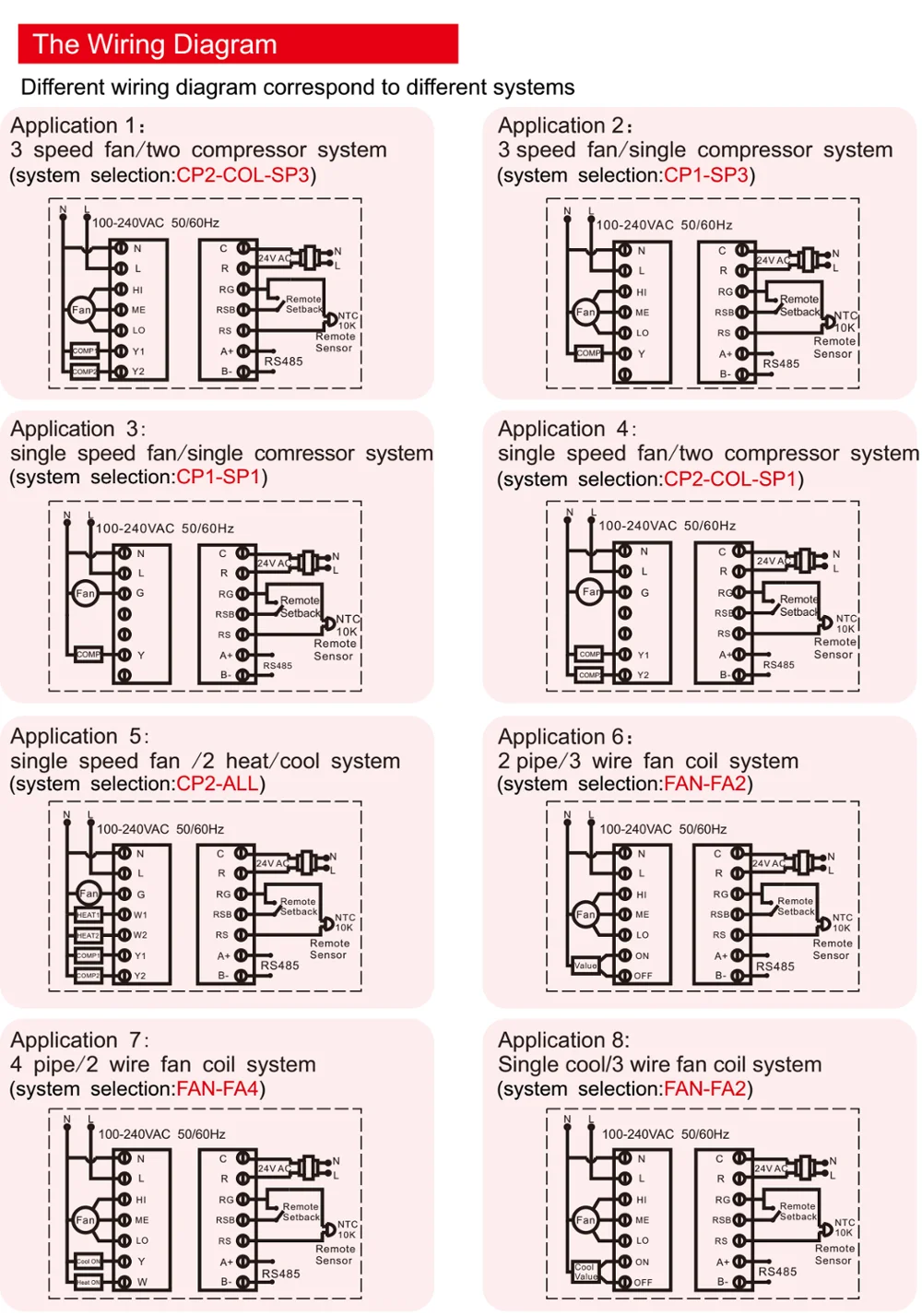
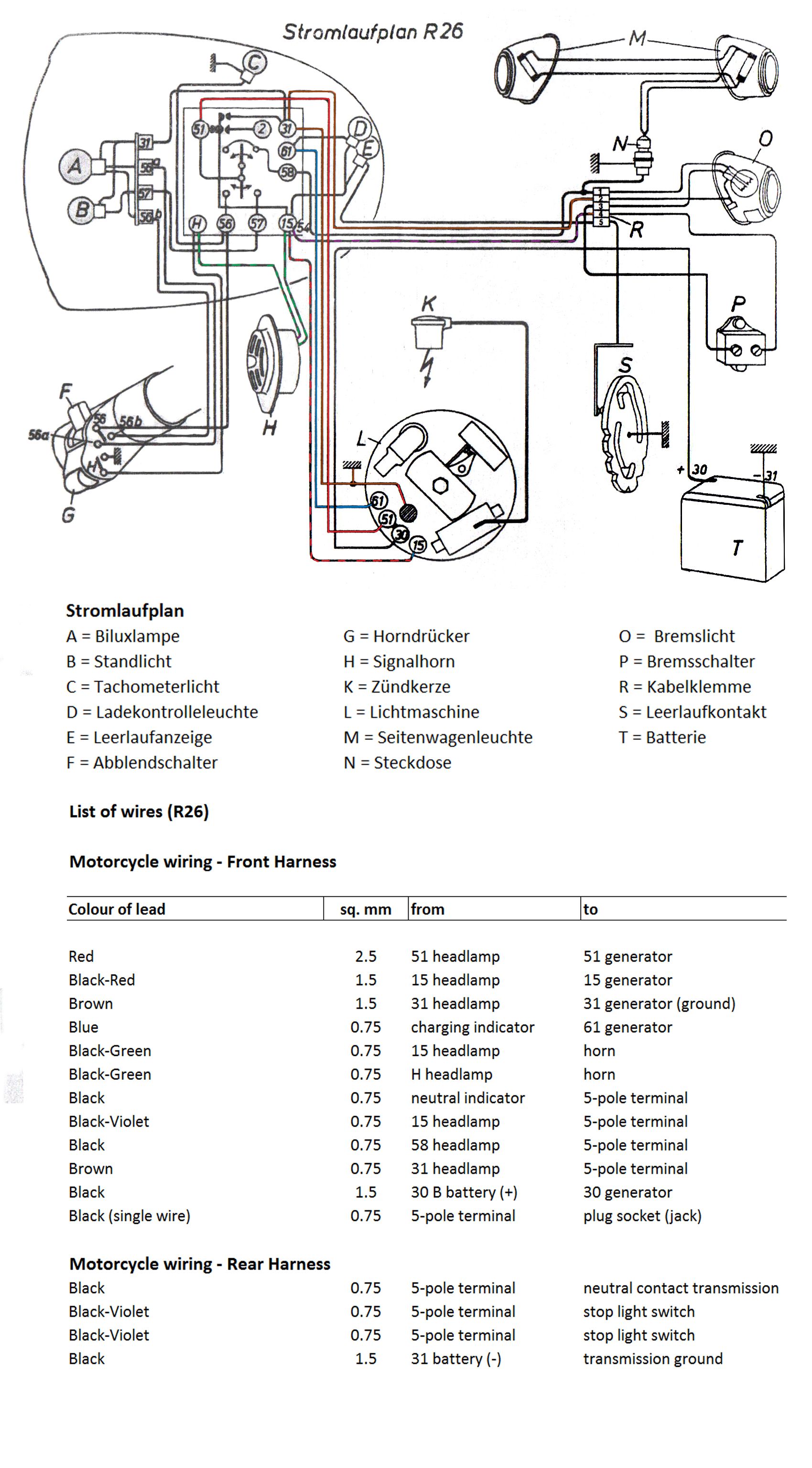
Dx 9100 wiring diagram. Dx 9100 on a din rail. The display is designed for the. It is designed for installation inside a control panel or on the controlled equipment via din rail. Dx 9100 digital controller version 1. Application specific controllersdx 9100 digital controller version 1 3 installation the dx 9100 digital controller version 1 has field wiring terminals inside the controller enclosure. It is designed for installation inside a control panel or on the controlled equipment via din rail.
6 configuration guidesdx 9100 configuration guide the dx 9100 has two packaging styles. When using the dx 91009120 product line for listed smoke control there are only two io restrictions. All field wiring with the exception of the n2 must be kept in the room the controllers are mounted in. Versions 2 and 3. Dx 9100 on a din rail extension modules. In version 1 all terminals for field wiring are located within the controller enclosure.
The dx 9100 xxxxf base must be used. Gx 9100 software configuration tool users guide 1 3 dx lcd display the dx lcd display unit is a personcontroller interface used with the dx 9100 series of controllers. All field wiring with the exception of the n2 must be kept in the room the controllers are mounted in.
