Dvc6200 sis dvc6200 sis instruction manual d103557x012 safety manual for dvc6200 sis d103601x012 dvc6200f dvc6200f instruction manual d103412x012 dvc6200p dvc6200p instruction manual d103563x012 sis. Parts and procedures are common across the dvc6200 series.

Emerson Fieldvuedvc6200 Instruction Manual Manualzz
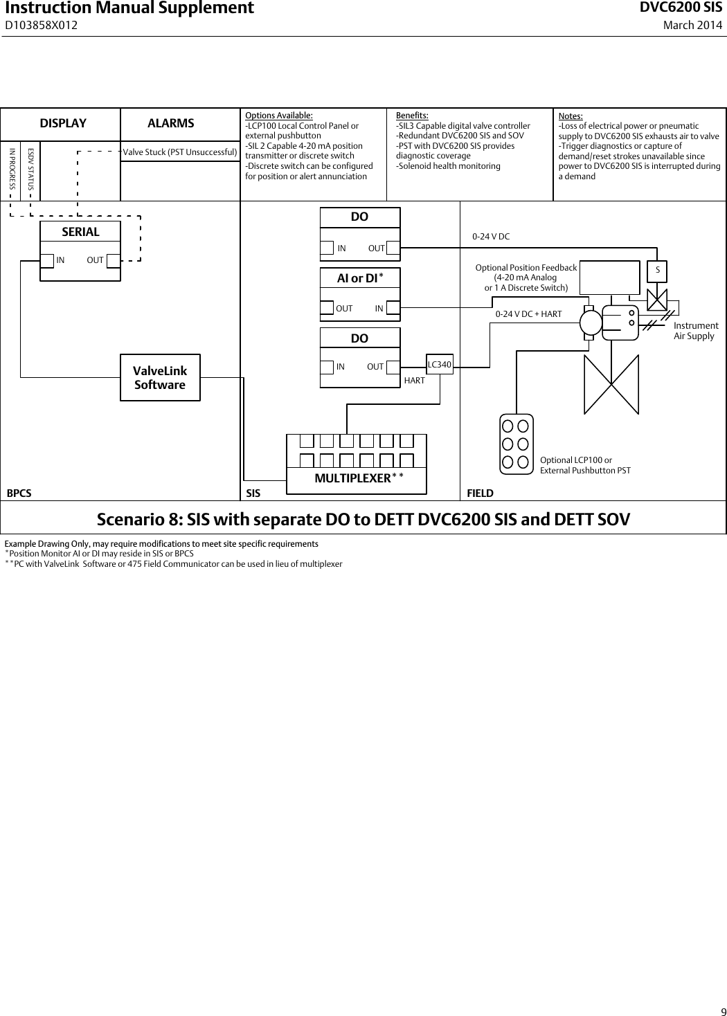
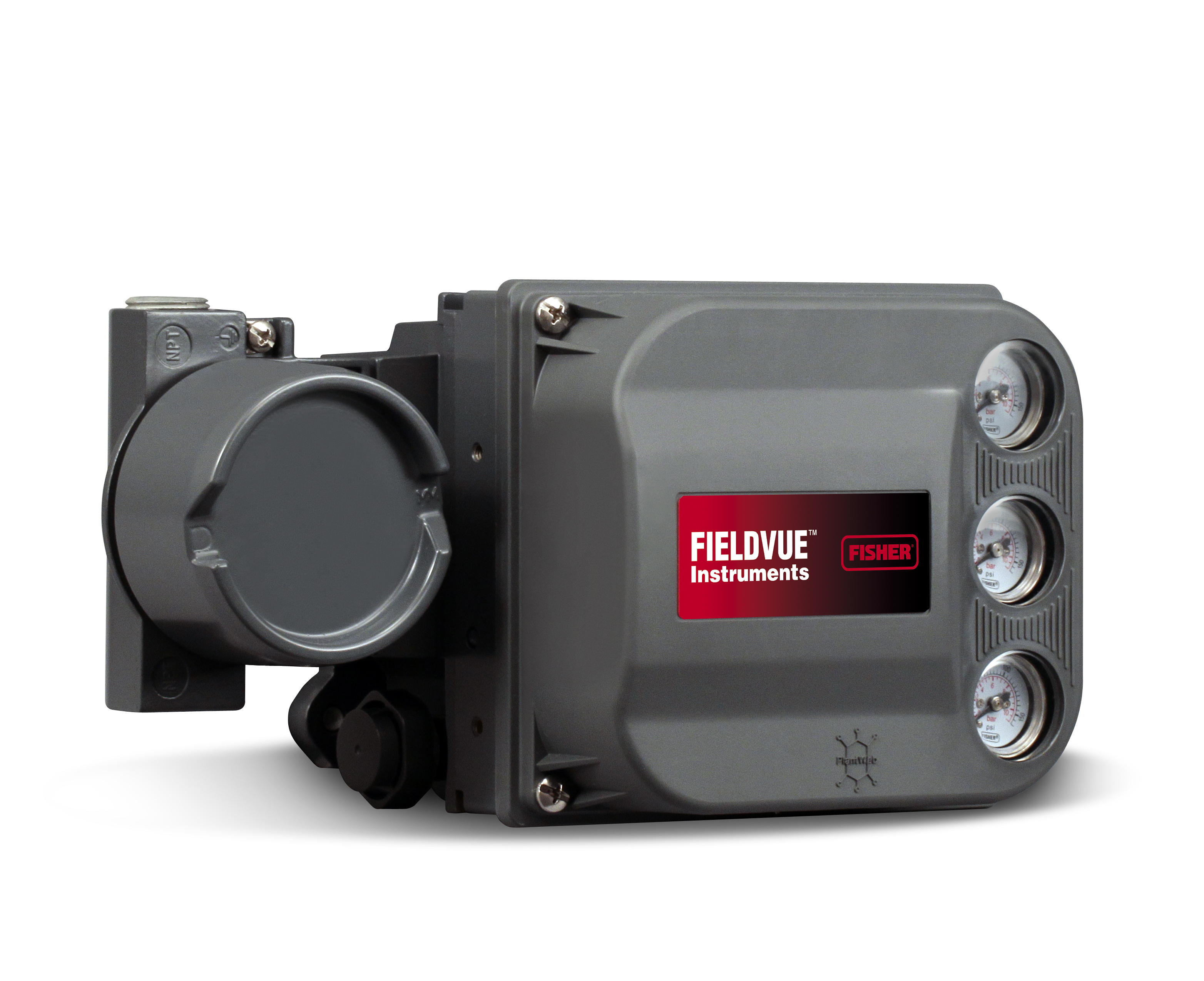
Dvc6200 sis wiring diagram. Fisher fieldvue dvc6200 sis digital valve controller for safety instrumented systems sis the fieldvue dvc6200 sis digital valve controller is a. The fisher fieldvue dvc6200 sis digital valve controller is capable controlling the valve safety shutdown function and safely extending time between proof tests using partial stroke testing all while monitoring the health of the entire valve assembly. Dvc6200 sis digital valve controllers figure 11 are hart communicating microprocessorbased currenttopneumatic instruments. Drawings indicated as pst only. Page 126 instruction manual principle of operation may 2013 d103409x012. Page 2 instruction manual supplement dvc6200 sis.
Enhance safety and reliability of your safety instrumented system sis valves. Instruction manual wiring practices d103605x012 february 2017 section 2 wiring practices22 control system requirements there are several parameters that should be checked to ensure the control system is compatible with the dvc6200 digital valve controller. Field ruggedized and portable tools enable easy valve setup and. Fieldvue dvc6200 sis digital valve controller block diagram valve travel feedback printed terminal box wiring board drive signal output a pneumatic converter relay supply pressure 4 20 ma output b hart vent valve and actuator input signal. The dvc6200 sis digital valve controller has three fundamental functions. Diagnostic tests can be run locally with ease and mobility using the 475 field communicator with valvelink mobile software.
Safety partial stroke testing pstthis is a small ramp. Catwalks ladders or other difficult locations no longer present a barrier. Modulate a pneumatic output to a valve actuator in response to a demand signal from a logic solver to move the valve to a safe state. The dvc6200 sis can operate through a command signal from either a dcs basic process control system bpcs or logic solver safety instrumented system sis. Fieldvue dvc6200 digital valve controller block diagram input signal 4 20 ma hart valve travel feedback printed wiring board drive signal terminal box output a auxiliary terminals pneumatic converter relay supply pressure. These are basic schematics that have been developed to provide details of the connections between the control system and user interface.
A weathertight wiring terminal box isolates field wiring connections from other areas of the instrument. Quick start guide d103556x012 dvc6200 digital valve controllers june 2019 3 before you begin. Page 1 safety manual for dvc6200 sis digital valve controller d103601x012 sections pertaining to the position monitor fisher fieldvue dvc6200 sis instruction manual d103557x012 failure to use this instruction manual supplement in conjunction with the above referenced manuals could result in personal injury or property damage.
