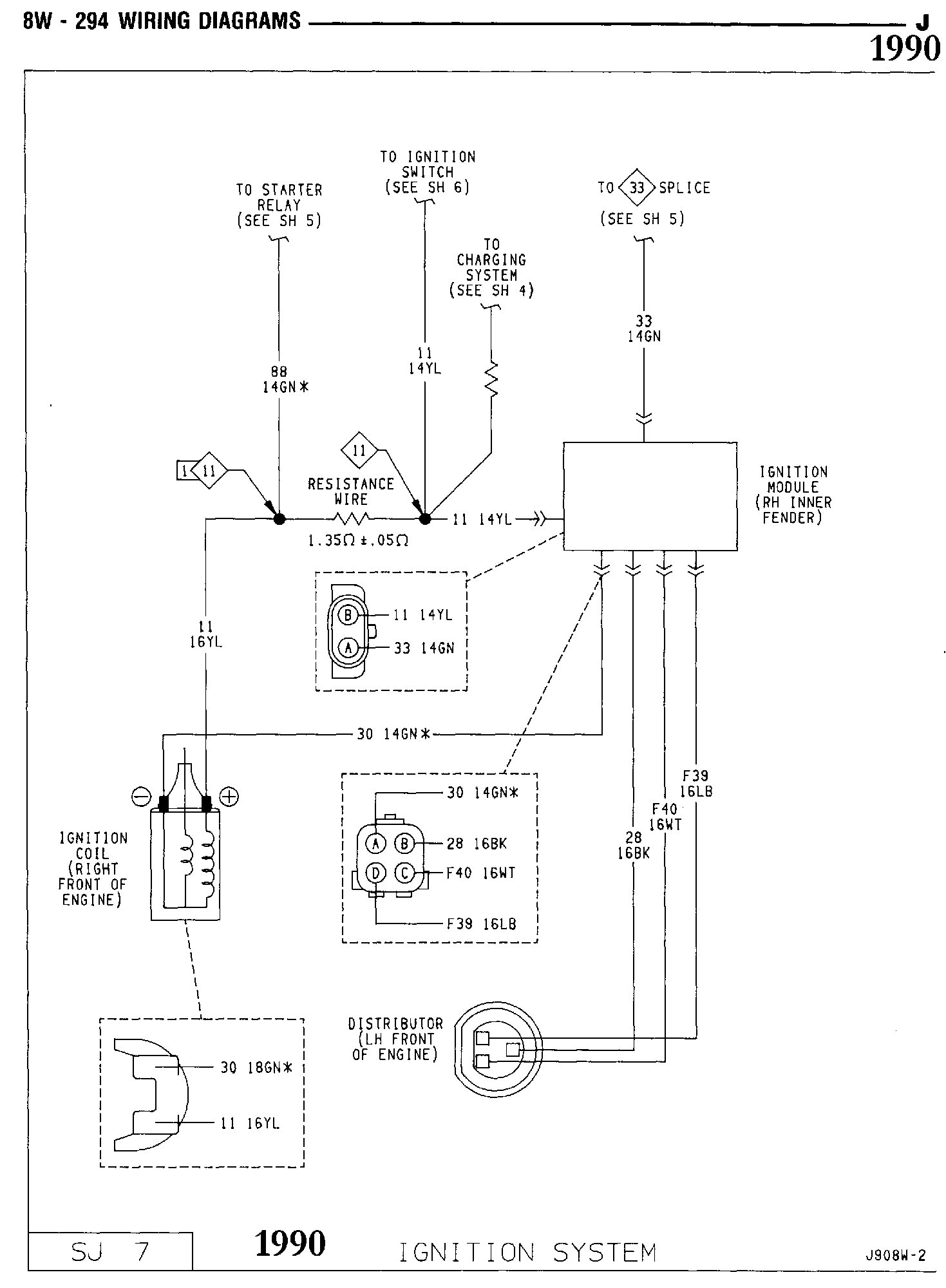
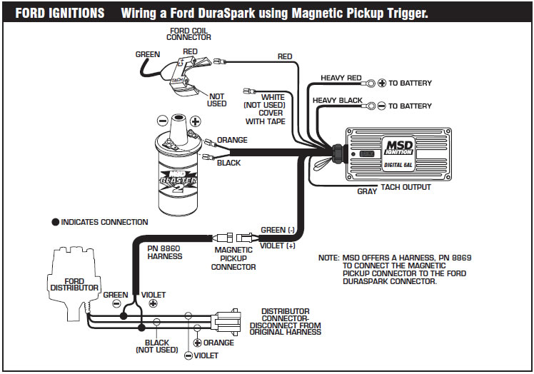
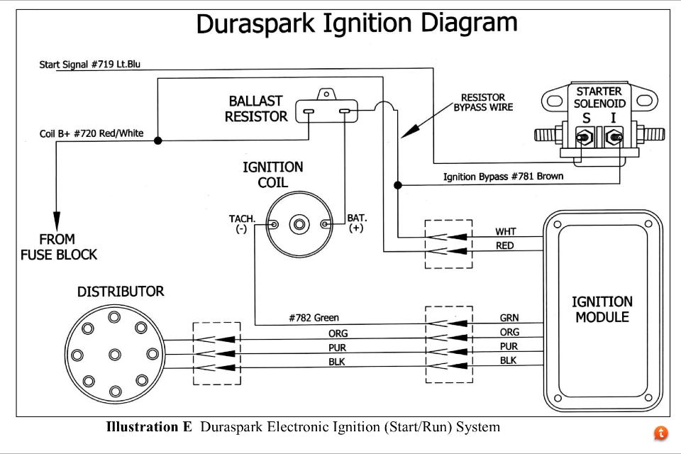
You can find the 1994 1995 ignition system wiring diagram here. If you replace the ignition wire keep in mind that all older fords used a if you are getting voltage to the coil the next thing to do is test the coil for spark with out the distributor or ignition module as the trigger.
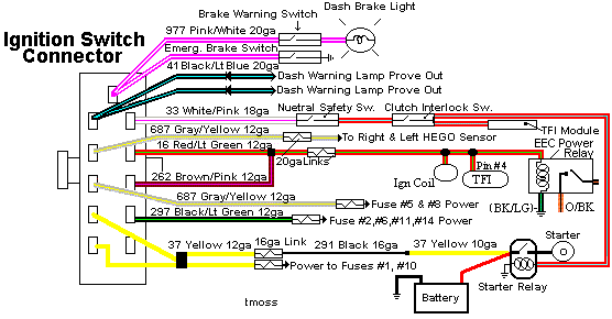
Carb 302 Ignition Wiring Mustang Forums At Stangnet
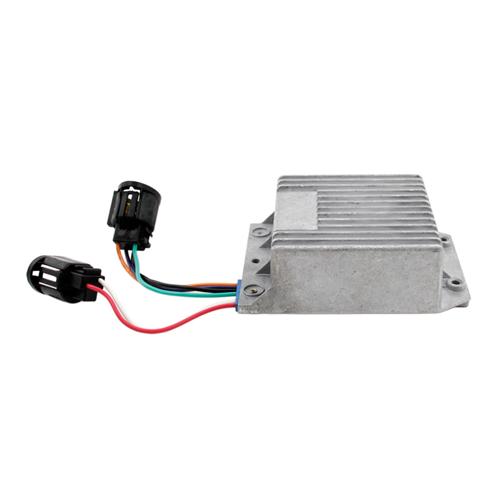
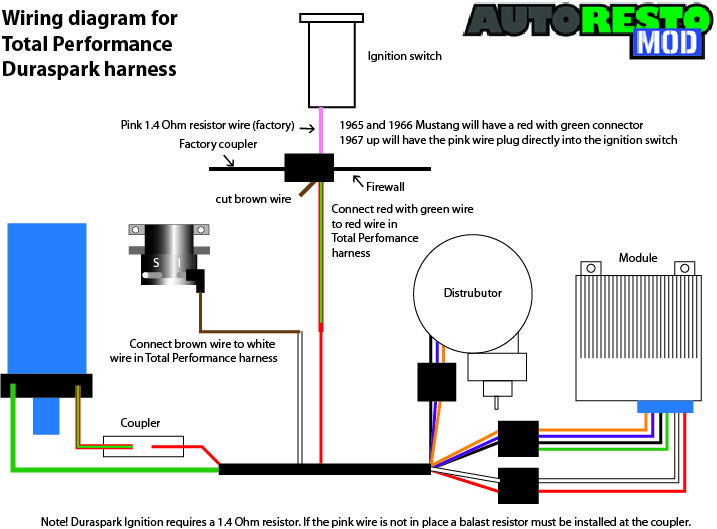
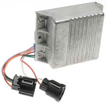
Duraspark ignition module wiring diagram. The duraspark ii control module has a blue strain relief bushing one 4 pin connector and one 2 pin connector. Disconnect the negative battery cable. You can find the ignition control module test explained here. Run a positive feed wire from ignition switch for when key is in the on position to the ignition module red wire coming out of ignition module. Shown here on the firewall of my 72 bronco. Dy204 module red sealing block aka.
The duraspark ii distributor uses a magnetic pickup in place of traditional breaker points. Ford ignition system circuit diagram 1994 1995 49l 50l and 58l. Duraspark ii ignition harness. Nov 23 bullnose f f larger f series trucks duraspark 2 tach wiring hey guys i have a ford maverick 5l in my rx7. I have it running and stuff but i cannot seem to make the tachometer work. Duraspark wiring diagram wiring diagram is a simplified good enough pictorial representation of an electrical circuitit shows the components of the circuit as simplified shapes and the power and signal connections amid the devices.
With a duraspark system there are no points as it is the function of. This duraspark ii ignition harness is designed to connect the components in ford electronic ignition systems using the blue strain relief ignition module. It can be used with both the large cap and small cap early electronic distributors. How to test the ford ignition control module. The duraspark ii ignition coil is capable of generating a higher voltage than the regular coil. Grommet deleted coil resistor low impedance high energy ignition coil the duraspark i system coil charging currents are higher than the duraspark ii and designed to achieve better emissions and mileage through more complete charge burning and improved ignition of lean airfuel mixtures.
A wiring diagram usually gives opinion approximately the relative aim and contract of devices and terminals on the devices to back in building or servicing. 64 z code head specs. In the next page youll find the icm connectors pinout with a brief description of each wire.

