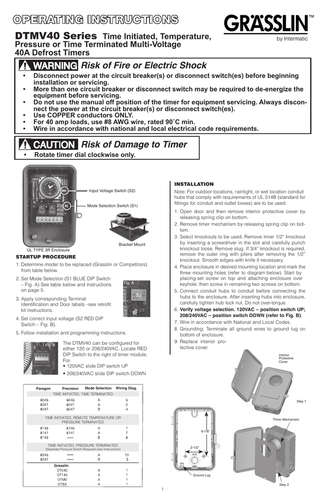
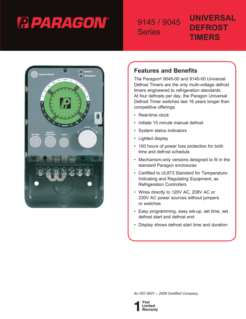
The dtav40 defrost timer is equivalent in function terminal identification with appropriate terminal block label attached and wiring to the paragon and precision series defrost timers. The dtav40 defrost control automatically selects the appropriate voltage between wiring diagrams.

Intermatic Defrost Timers And Manuals
Dtav40 wiring diagram. The wires on your new switch are intended for black power. Check your wiring it sounds like its not right. Grasslin dtav40 wiring diagram for electric heat hot gas or compressor shutdown defrost the grasslin dtav40 series auto voltage defrost timer is applicable to air defrost compressor intermatic grasslin s defrost controls just got even better the dtav40 defrost control automatically selects the appropriate voltage between wiring diagrams check your wiring it. Dtav40 typical wiring diagrams all switch positions are shown in refrigeration cycle operation and change position upon initiation of a defrost. Grasslin dtav40 wiring diagram. Page 3 dtav40 typical wiring diagrams all switch positions are shown in refrigeration cycle operation and change position upon initiation of a defrost.
And red lights. 1 thermostat compressor or solenoid valve or contactor coil defrost heater l1 l2 1 2 4 x 8041 replacement 2 mode a with 8041 terminal block label applied 8041 3 label fan line n 3 l1 l2 2 2. The dtav40 may also be used to replace paragon and dtav40 wiring diagram. 8145 replacement 8247 replacementdouble pole switching 8041 replacement mode b with 8247 terminal block label applied mode a no label required mode a with 8041 terminal block label. 1 thermostat compressor or solenoid valve or contactor coil defrost heater l1 l2 1 2 4 x 8041 replacement 2 mode a with 8041 terminal block label applied 8041 3 label l i n e fan n 3 l1 l2 2 2. Dtav40 typical wiring diagrams all switch positions are shown in refrigeration cycle operation and change position upon initiation of a defrost.


