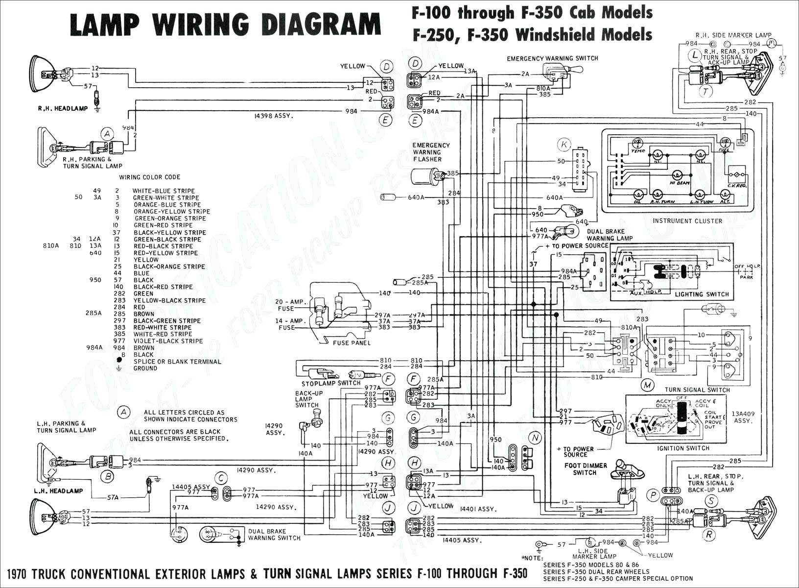
Autorestomod manic mechanic gasoline media 35479 views. Cummins to ford alternator wiring diagram.
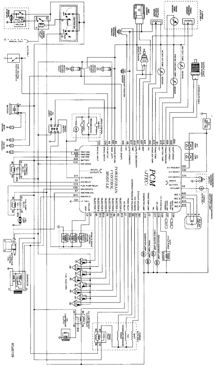
9c7488 1971 Dodge Challenger Alternator Wiring Diagram
Dodge alternator wiring diagram. Dodge alternators ground themselves through their case except 100 amp alts through the bracketry the engine block then finally to the battery negative terminal through the negative. Alternator basics tips tricks 1 wire models of gm ford mopar from 1960 1980s autorestomod episo duration. The alternator charge wire routes direct to the battery and not through any switch connection the alternator will not operate correctly if not connected direct to battery or directly through the ammeter. Diagram 1 shows the basics of the early alternator voltage regulator design. Most are near the main power from the battery. We are concerned with pin 25 in the grey c3 connector as it is the opposite end of the dark blue wire at the alternator.
The connector in the middle is the white c2 connector. This is an engine compartment wiring diagram for a 1969 valiant. Jump to latest follow. A forum community dedicated to dodge cummins diesel truck owners and enthusiasts. In most maybe all factory wiring the alternator output wire will be black. Electrical diagrams for 1960s and 1970s chrysler dodge and plymouth cars for use with alternator and electronic ignition upgrades or troubleshooting.
A fusible link is a short 6 wire spliced into a main wire and has a rubber bump moulded onto it. Reference the wiring diagram at the pcm. Nowadays 60 amps would be small and 100 amps is common. We are also concerned with pin 10 of the white c3 connector as it is the opposite end of the green wire at the alternator. Variety of dodge alternator wiring diagram. If i remember correctly the center post has to go to ign and either terminal on the alt and the other wire goes straight to the alternator.
After studying the wiring diagrams i discovered that per the dodge factory service manual a 35 amp was standard while a 60 amp heavy duty alternator was optional and the wiring was different for that option. There are 2 brushes in the alternator each one has a field terminal one is labeled fld the other is labeled gnd. The wiring that comes with our kits should be used as it is sized to handle the amperage. My 71 van has between the battery terminal and bulkhead connector that connects to the ammeter. Come join the discussion about. My 78 van has several one from the battery and a few others inline near the battery.
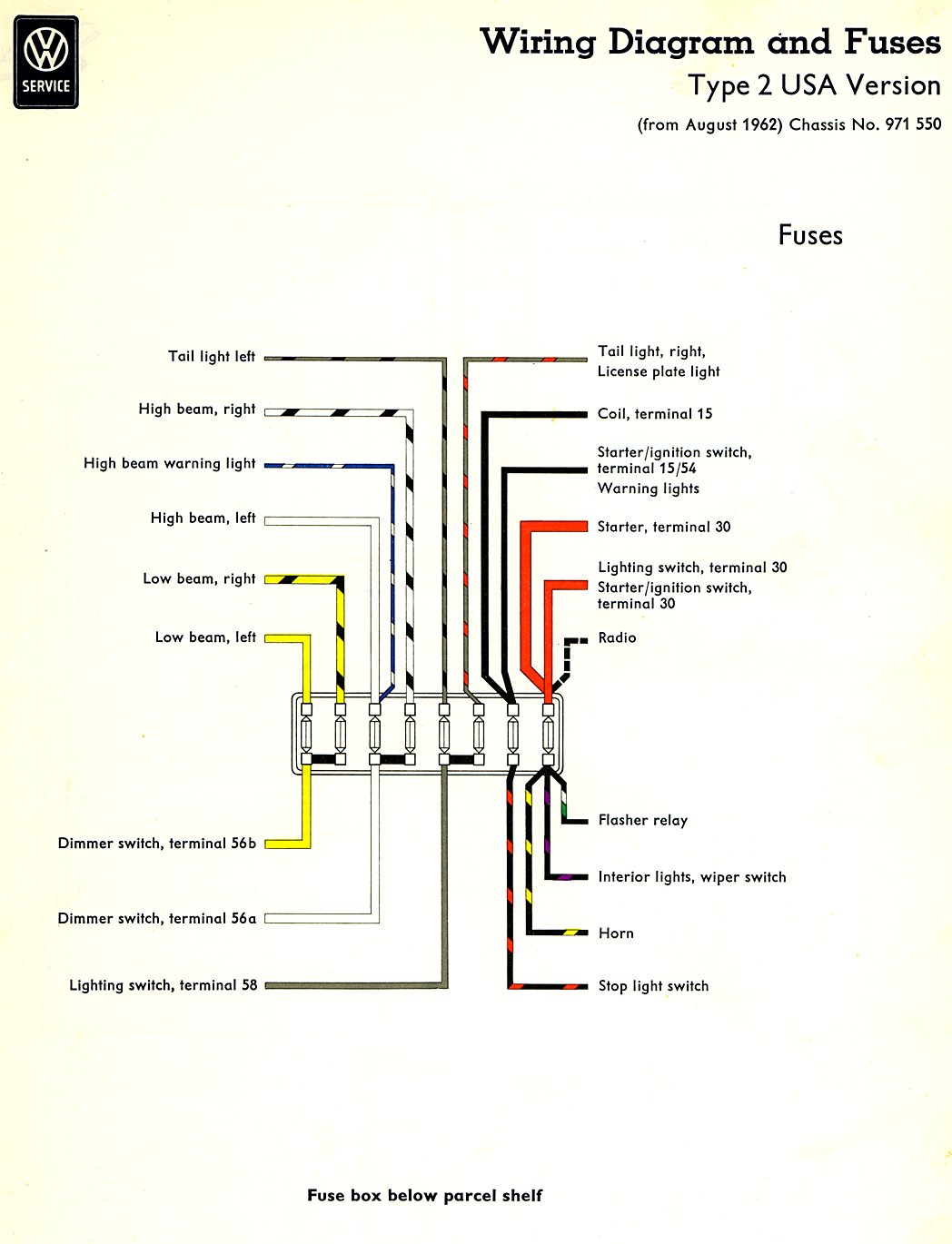
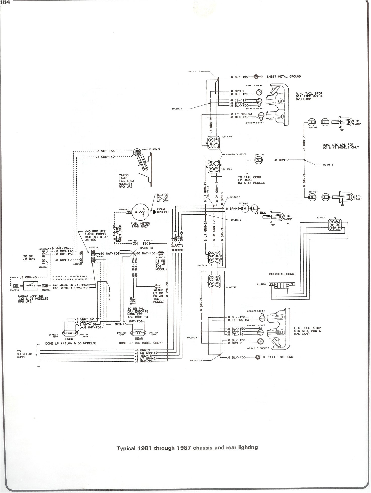
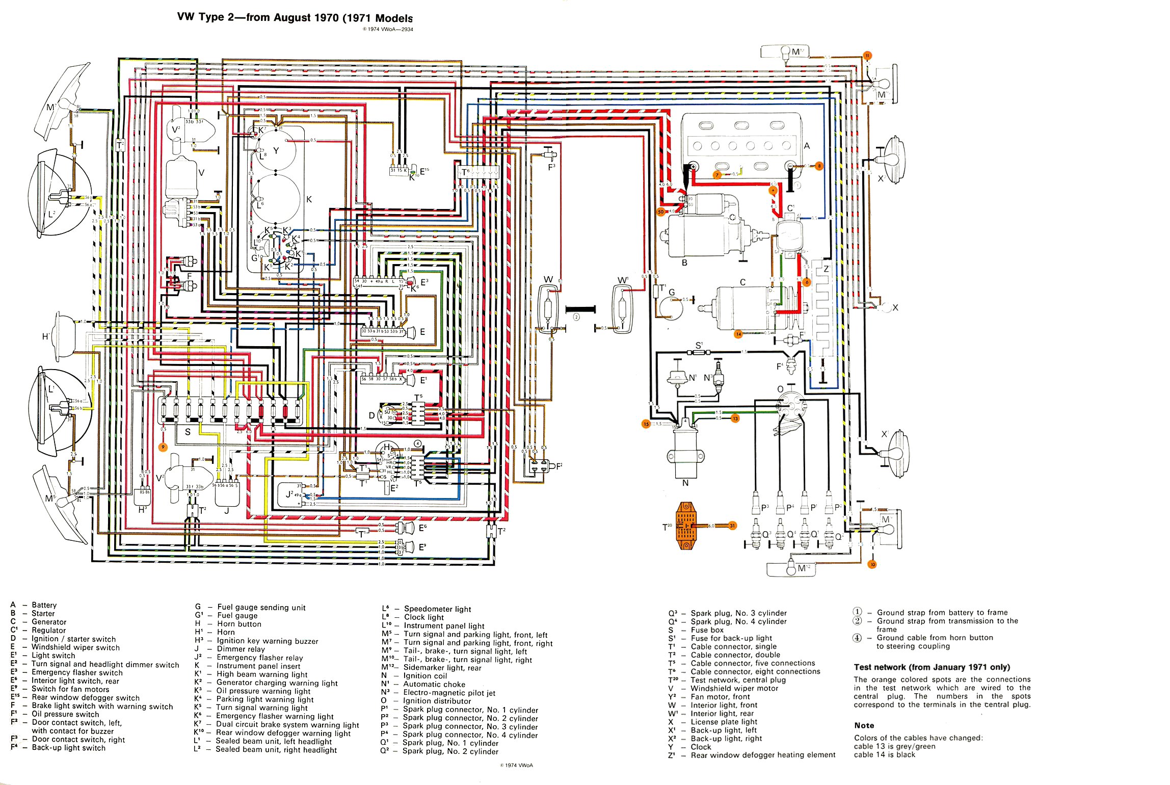
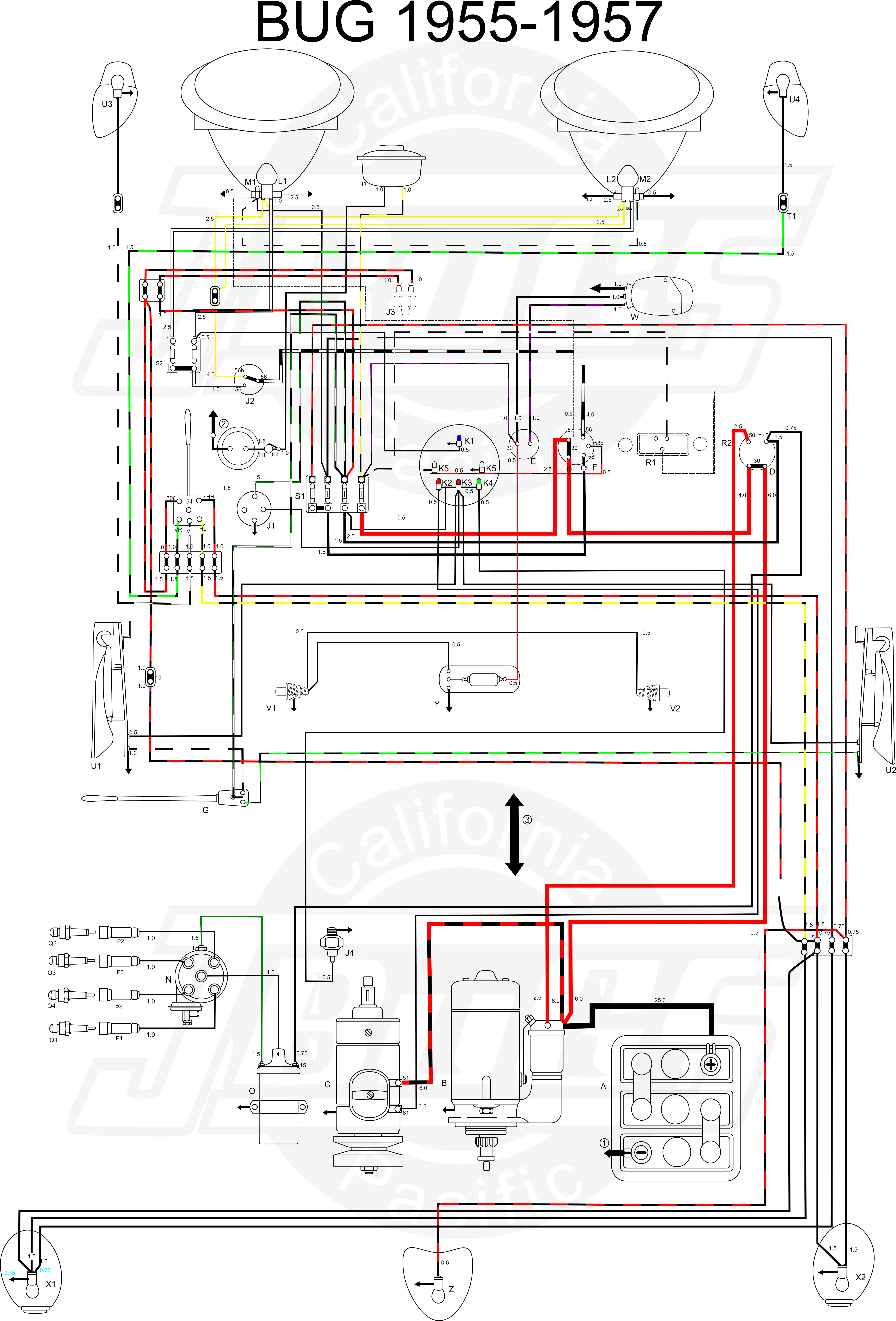
I have been running a 60 amp alternator for about 8 years now. B bodies had a horn relay rather than the horn button activating the horn directly. It shows the components of the circuit as streamlined shapes as well as the power and also signal links in between the tools. A wiring diagram is a simplified standard photographic depiction of an electrical circuit. Other than that they were very similar. I have shown the main alternator output wire in the above diagram in red.
The gnd brush is grounded with the brush mounting screw.


