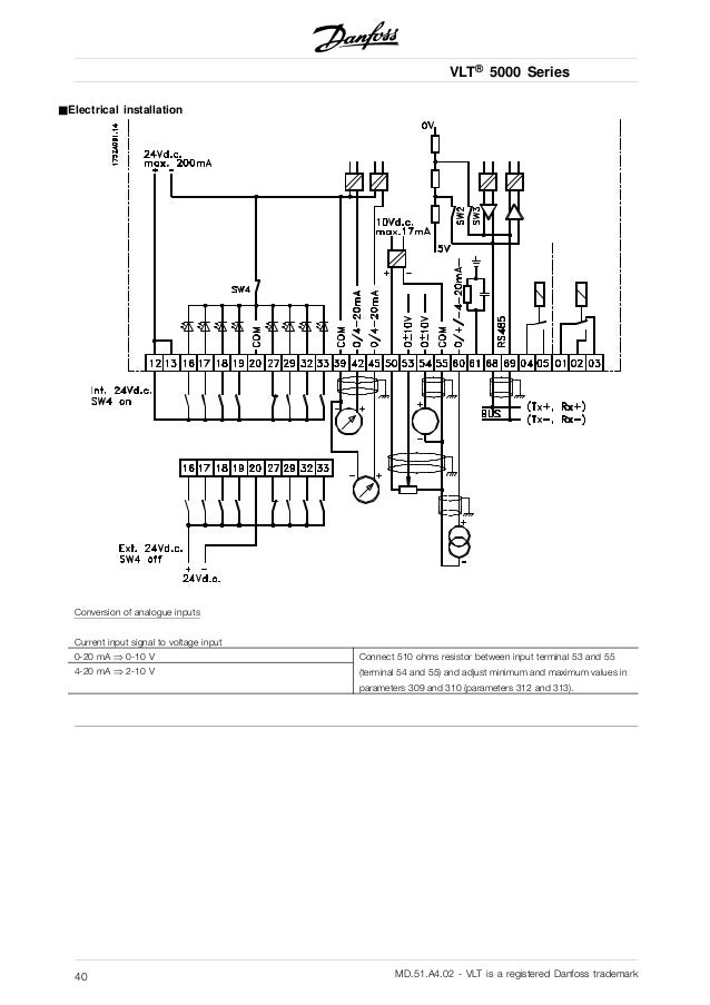
Wiring of mains and motor connections. The drive is programmable and offers many features and savings compared to operating a motor from unregulated line voltage.
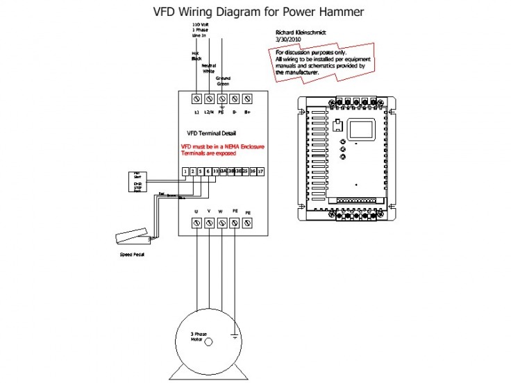
Danfoss Vfd Wiring Diagram Diagram Base Website Wiring
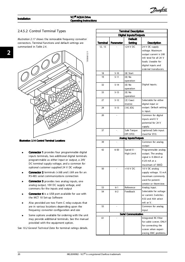
Danfoss vfd wiring diagram. Vfd connection diagram inputoutput in hindi by gopal sir duration. The panel is a protective enclosure in which the drive and various optional components are assembled and mounted. A variable frequency drive regulates the speed and operation of an electric motors. Danfoss mobile apps software and pc tools empower your vfd by providing easy selection operation and customization. Danfoss drives remains open and is doing our part to support essential industry. Wiring of control and serial communications.
523 signal and power wiring consideratio ns for electromagnetic compatibility 41 524 effects of emi 42 525 sources of emi 42 526 emi propagation 43 527 preventive measures 44 6 test procedures 45 61 non repairable units 45 62 introduction 47 63 static test procedures 47 632 rectifier circuit test 48 633 inverter section tests 48. The installation guide is intended for use by qualified personnel. Detailed tests that must be performed before start up. 15 block diagram of the frequency converter illustration 11 is a block diagram of the frequency converters internal components. Maximize the performance of your variable frequency drive with quality software to support it. Control terminal functions.
Acdc drivevfd control terminal wiring diagram and concept हद म a for automation. Save energy improve control and reduce motor wear using ac drives also known as variable speed drives vsd inverters ac inverter drives ac drive inverters ac vfds hvac drives or variable frequency drives vfd. 35 wiring schematic 16 36 controls 18 361 control principle 18 362 fc 301 vs. Option panel used in conjunction with a danfoss variable frequency drive vfd or drive. 44 wiring schematic 12 45 access 14 46 motor connection 14 47 ac mains connection 17 48 control wiring 17 481 control terminal types 17 482 wiring to control terminals 19 483 enabling motor operation terminal 27 19 484 voltagecurrent input selection switches 19 485 safe torque off sto 20 486 rs 485 serial communication 20. 7111 fixed variable speed pump wiring diagram 127 7112 lead pump alternation wiring diagram 127 7113 cascade controller wiring diagram 128 7114 startstop conditions 129 8 installation and set up 130 81 installation and set up 130 82 fc protocol overview 131 83 network configuration 132 84 fc protocol message framing structure 132.
To enable efficient handling of the equipment. Initial programming to verify proper functioning of the drive system. Fc 302 control principle 19 363 control structure in vvc 20 364 control structure in flux sensorless fc 302 only 21 365 control structure in flux with motor feedback fc 302 only 22 contents vlt automationdrive fc 301fc 302 design guide 025 75 kw.

