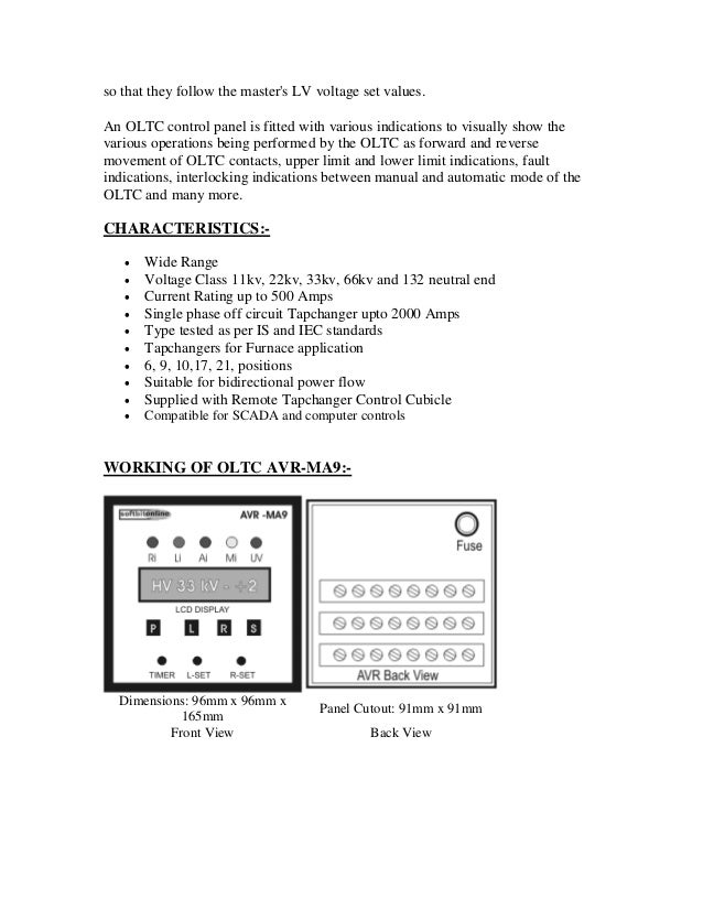
Ready to install and use with any make of oltctransformer. After the initiation the switching.

Abkurzungs Liste Abklex Familie Alex Weingarten Baden
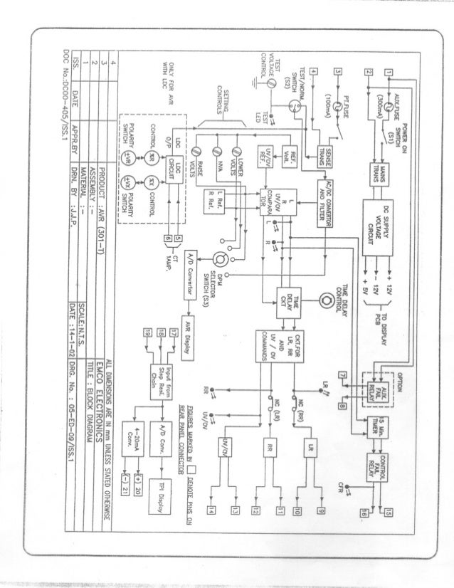
Ctr oltc wiring diagram. 11 kv 17 position linear 200 amps dm08. 3ø wiring diagrams 1ø wiring diagrams diagram er9 m 3 1 5 9 3 7 11 low speed high speed u1 v1 w1 w2 u2 v2 tk tk thermal overloads two speed stardelta motor switch m 3 0 10v 20v 415v ac 4 20ma outp uts diagram ic2 m 1 240v ac 0 10v outp ut diagram ic3 m 1 0 10v 4 20ma 240v ac outp uts these diagrams are current at the time of publication. See appendix circuit diagram 4 71 529 421 control the motor drive control follows the step by step principle ie. The above figure shows the elementary form of on load tap changer oltc. 33 kv 21 position linear 300 amps eo09. Separate rtcc panel not required.
Operation maintenance manual for on load tapchangers type abs ss 1. 33 kv 17 position linear 300 amps en20. Two fingers a and b are movable and connected with the centre tapped reactor through switches x and y. This model se avr96 can be fitted into ht panel with minimal wiring scheme. The transformer tappings are connected to the segments 1 to 5. Complete oltc control and monitoring system.
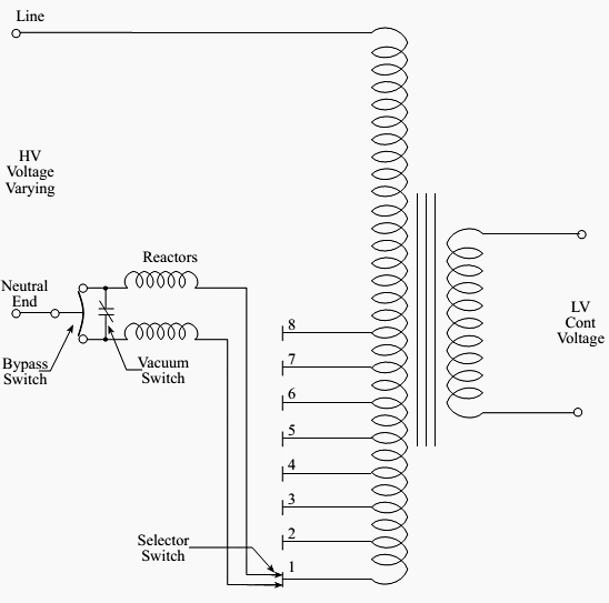
22 kv 9 position linear 300 amps dm16. It shows the components of the circuit as simplified shapes and the capacity and signal links between the devices. 33 kv 9 position linear 300 amps en16. Complete with a color coded trailer wiring diagram for each plug type this guide walks through various trailer wiring installation solution including custom wiring splice in wiring and replacement wiring. Schematic diagram of oltc. The zone indication disc has a sector painted in green and the centre of the green zone has a red.
For example if we need that motor 1 should stop when motor 3 starts to run then we may use a normally close nc link of m3 in line 1. Cl08 11 kv 9 position linear 300 amps cm08 11 kv 9 position linear 200 amps cm16. Built in voltage control tap measurement and oltc status indications features. 22 kv 17 position linear 300 amps el08. In short we may change the motors operation and control by doing some modification in the above simple electrical interlocking control circuit diagram. Operation is indicated by the red center mark in the green zone.
If your vehicle is not equipped with a working trailer wiring harness there are a number of different solutions to provide the perfect fit for your specific vehicle. The abs ss range of on load tapchanger is housed in a sheet steel tank. As shown in the figure the center tapped reactor c prevents the tapped winding from getting short circuited. 33 kv 17 position coarse. Ctr oltc wiring diagram wiring diagram is a simplified agreeable pictorial representation of an electrical circuit. 33 kv 10 position linear 300 amps eo16.


