Chromalox heat flo thermostat kit wiring diagram 1 of 2 for chromalox heatflo type kuh tk3 and kuh tk4 used only in kuh 02 through kuh 45 heaters. Circuit does not have a positive off.
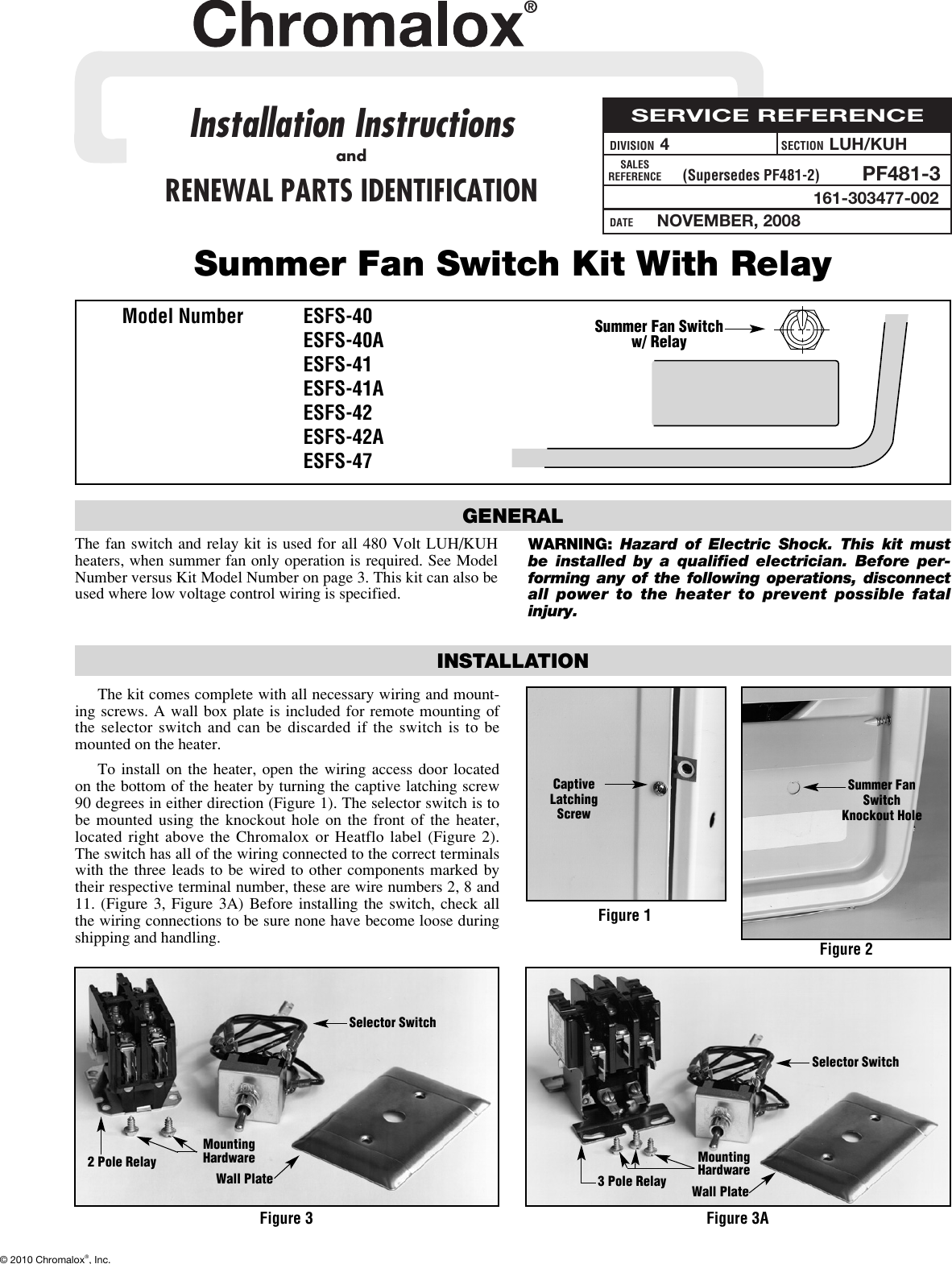
Chromalox Esfs 40 Users Manual Pf481 3 Chx
Chromalox luh wiring diagram. View and download chromalox luh tk1 installation operation parts online. Luh d 05 43 480 5000 3 60 30a 1 luh d 07 81 1 361 50a 1 luh d 07 83 208 7500 3 209 30a 1 luh d 07 21 1 311 30a 1 luh d 07 23 208240 56257500 3 181 25598 20 12 17 14 11 12 30a 1 luh d 07 71 277 7500 1 272 30a 1 luh d 07 43 480 7500 3 90 30a 1 luh d 10 81 1 480 50a 1 luh d 10 83 208 10000 3 278. More wiring diagrams are given in the chromalox heatflow. Remove the motor lead wires from the heater contactor terminals marked t1 t2 and t3. For chromalox luh series heaters. Luh horizontal blower heater 26 45 kw 8900 153000 btuh 208 240 277 480 and 600 volt 1 or 3 phase wall or ceiling mounted configurations refer to wr 80 rtc wr 90 in the controls section.
Typical heater wiring diagrams the following diagrams show typical heater wiring schematics. Three phase ac heater circuit where line voltage and current do not exceed thermostat rating. Chromalox thermostat kits hvh tk6 and hvh tk6 for field installation only in chromalox hvh 02 through hvh 15 heaters. Note that single phase motors will have only two lead wires 2. Single phase ac circuits where line voltage and current do not exceed thermostat rating. Page 3 wiring diagrams motor motor motor heating heating heating elements elements elements overheat overheat overheat cutout cutout contactor contactor cutout contactor transformer fuses l1 l2 l3 ground ground l1 l2 l3.
Description type luh self contained heater provides quiet.
