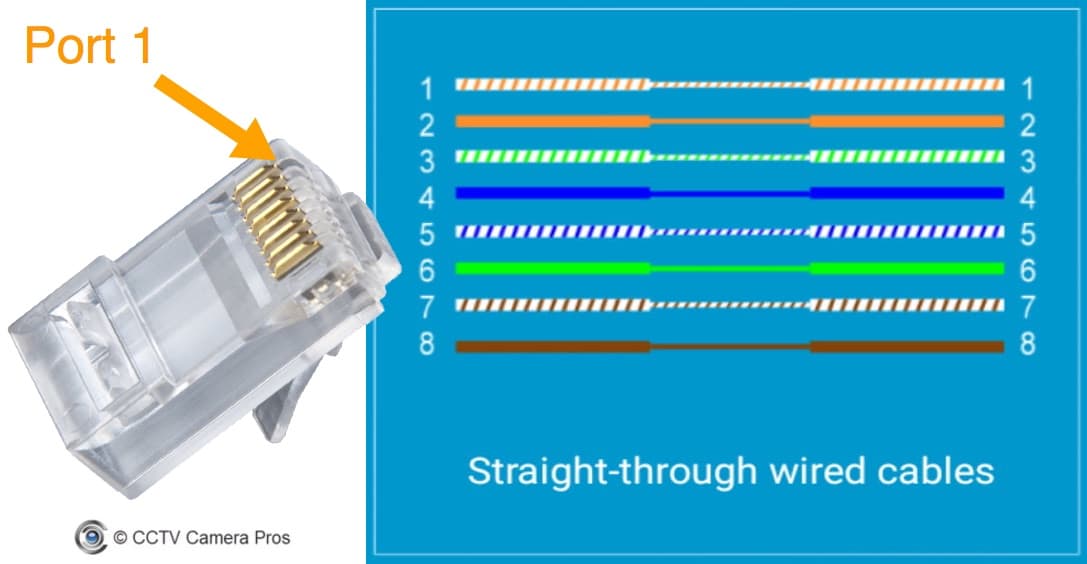
Cat5 straight diagram this diagram is used for straight through cables also called patch cables and theyre the standard ethernet cable used when youre connecting a device to a router switch or hub. Various ethernet network cables are being invented.

Cat5 Poe Wiring Diagram Escaperoomfortworth
Cat5 poe wiring diagram. Each component ought to be placed and connected with different parts in particular way. Cat5e cables can support 1000base t transmission up to 100 m which meet the requirements of various applications in our home office and data center. Here is a picture gallery about poe cat5 wiring diagram complete with the description of the image please find the image you need. Please note that these instructions are the same for cat 6 cable and and other type of 4 twisted pair network cable. Cat 5 wiring diagram crossover cable diagram regarding poe cat5 wiring diagram image size 600 x 340 px and to view image details please click the image. Otherwise the arrangement will not function as it should be.
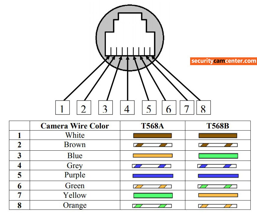
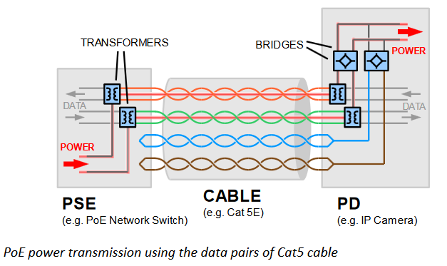
It has better performance than cat5 and lower price. Pinout of power over ethernet poe and layout of 8 pin rj45 8p8c female connector and 8 pin rj45 8p8c male connectorpower over ethernet is a technology that allows ip telephones wireless lan access points security network cameras and other ip based terminals to receive power in parallel to data over the existing cat 5 ethernet infrastructure without the need to make any modifications. The reason why the green cable is separated by the blue set is that it allows for longer cable runs up to 100m. They can support different transmission distances and applications. This cat5 wiring diagram and crossover cable diagram will teach an installer how to correctly assemble a cat 5 cable with rj45 connectors for regular network cables as well as crossover cables. Network cables like cat5 cat5e and cat6 are widely used in our network.
Poe ip camera wiring diagram poe ip camera wiring diagram every electric structure is composed of various diverse components. Cat 5 wiring diagram crossover cable diagram.


