Calling it a california 3 way seems to make sense. This might seem intimidating but it does not have to be.

Multiway Switching Wikipedia
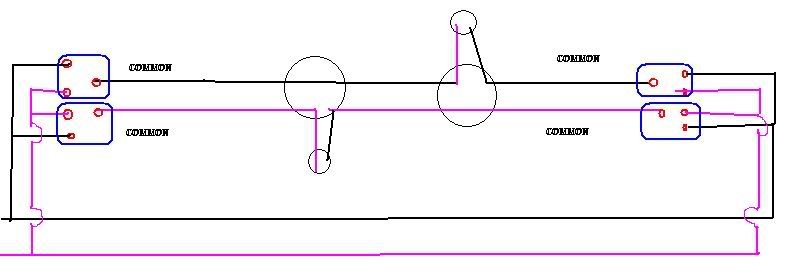
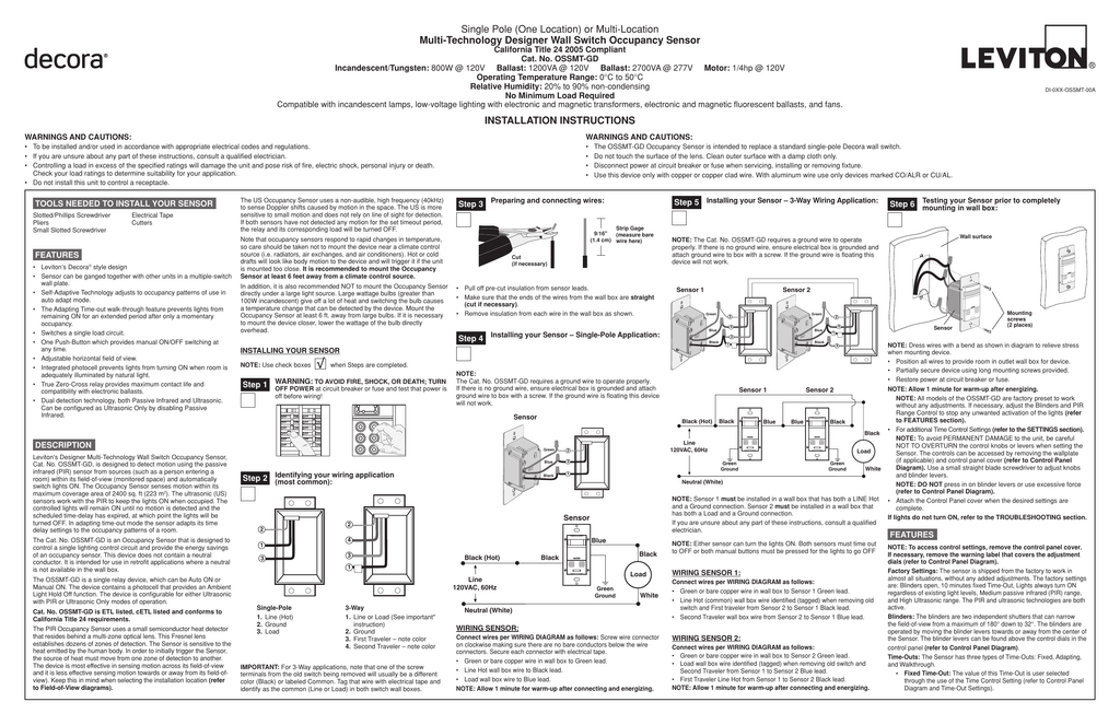
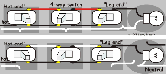
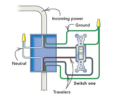
California 3 way wiring diagram. This is only a wiring schematic and not the actual wiring method used for 3 way switch installations. The alternate 3 way switch wiring configuration california or west coast was used as a way to wire 3 way switches and be able to supply line voltage to either switchthis configuration is no longer allowed as the neutral is not present in each switch box. How to wire 3 way switch. Wiring diagram 3 way switch with light at the end in this diagram the electrical source is at the first switch and the light is located at the end of the circuit. Pick the diagram that is most like the scenario you are in and see if you can wire your switch. The 2 diagrams below shows a 4 way added into the traveler wires and yet the light stays on even after the 4 way switch is flipped.
It is the best and easiest method of wiring 3 way switches. I have never ever seen this method to wire 3 way switches before. Three wire cable runs between the switches and 2 wire cable runs to the light. The black and red wires between sw1 and sw2 are connected to the traveler terminals. With these diagrams below it will take the guess work out of wiring. Also called a california 3 way.
Conventional and california diagram. Two very old three way switches are depicted in the photo above. And hope i never see it in the field. 3 way switch wiring diagram. Below is a simple schematic diagram that can be applied to all three way electrical light switch connections. Take a closer look at a 3 way switch wiring diagram.
Two very old three way switches. S3 method 4 two wire traveler. 3 way switch schematic wiring diagram. Conventional 3 way wiring is not very complexwith conventional wiring the line line voltage connects to the common of one switch.
