Network wiring instructions for rj11 and rj45 rj 11 telephone plug. The complete ethernet pinout cable wiring reference with wiring step by step guide.

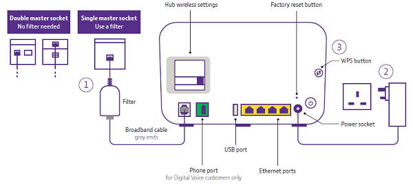
Bt Home Hub 5 Wiring Diagram Romans 8 Block Diagram Volume
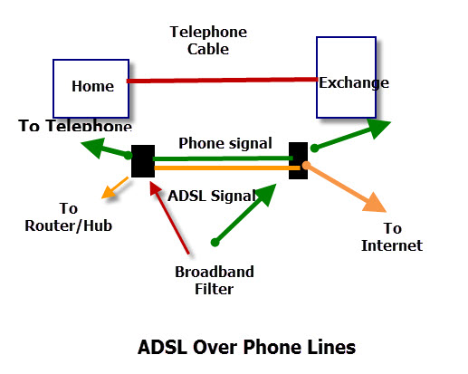
Broadband wiring diagram. Also ive seen a lot of cases where they star the wiring from a lju and not run it in a daisy chain. Wireless diagrams voip diagram dsl diagram wireless 10mbps or greater ubiquiti 15mbps 3mbps canopy voip phone service dsl. If you have fibre to the home have a look at fibre to the home. I am trying to wire in an extension socket for broadband. This is how the telephone wiring colour code looks wired with the stripey telephone cable. Wiring a broadband extension socket from a bt master any help would be appreciated.
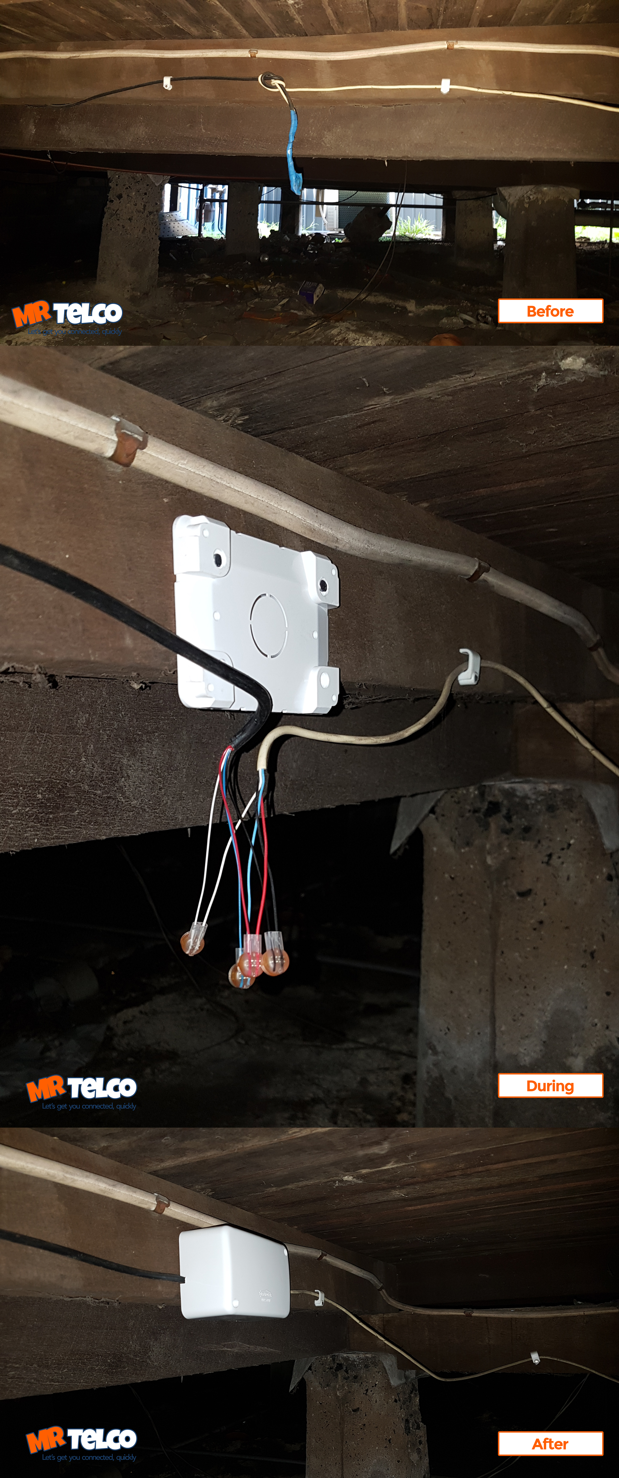
The diagram is shown with the hook clip on the underside. Click to find view print and more. Problem is when developers install internal wiring they tend to use the cheapest stuff going. The phone works from the extension but when the router is plugged in to the extension. Click to check the right one for you or print as reference. If youre having trouble with your broadband a few simple checks can get you up and running again.
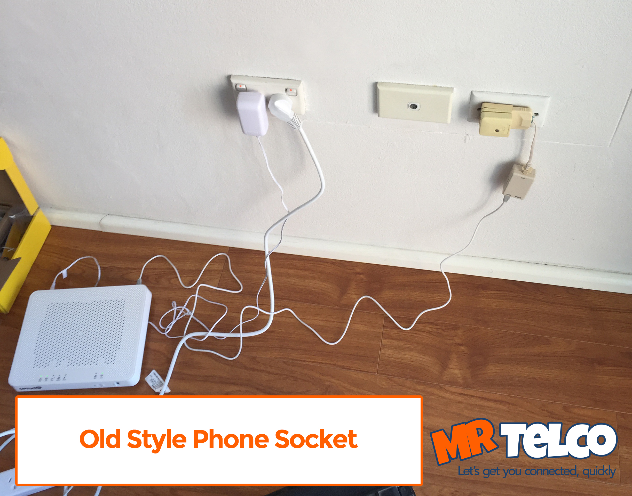
I have connected the extension cable to pins 3 5 and 2 at the master socket and similarly to the extension socket. Yes internal wiring is a massive killer of broadband especially vdsl. Each network diagram includes a description of the pros and cons of that particular layout as well as tips for building it. Check your wiring and set up for information. Otherwise follow the instructions below. First youll need to check your type of master socket.
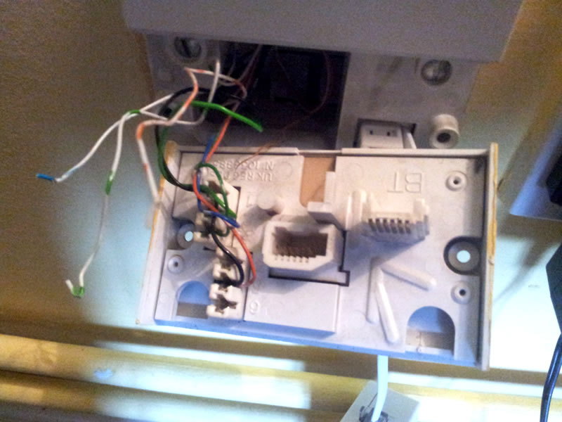
Rj11 wiring diagram rj11 socket wiring diagram rj11 splitter wiring diagram rj11 wiring diagram every electric arrangement consists of various diverse parts. You can see the test socket revealed to allow you to check the bt line before your own wiring. Remember the rj45 wiring order. This is the telephone wiring colour code for the nte5 bt master socket with the cable feeding extension sockets attached to the customer removable front plate. Each part ought to be placed and linked to other parts in specific way. Many home network layouts work fine but most are variations on a basic set of common designs.
The usual elements in a wiring diagram are ground power supply cord as well as connection result tools buttons resistors reasoning entrance. This gallery contains network diagrams for wireless wired and hybrid home networks. Figure 1 is the wiring scheme for the plug side of an rj 11 connector. The typical rj 11 connector has six terminals. Otherwise the structure wont function as it ought to be. To read a wiring diagram initially you need to understand exactly what fundamental components are included in a wiring diagram and also which pictorial signs are made use of to represent them.
Rj45 pinout diagram shows wiring for standard t568b t568a and crossover cable.

