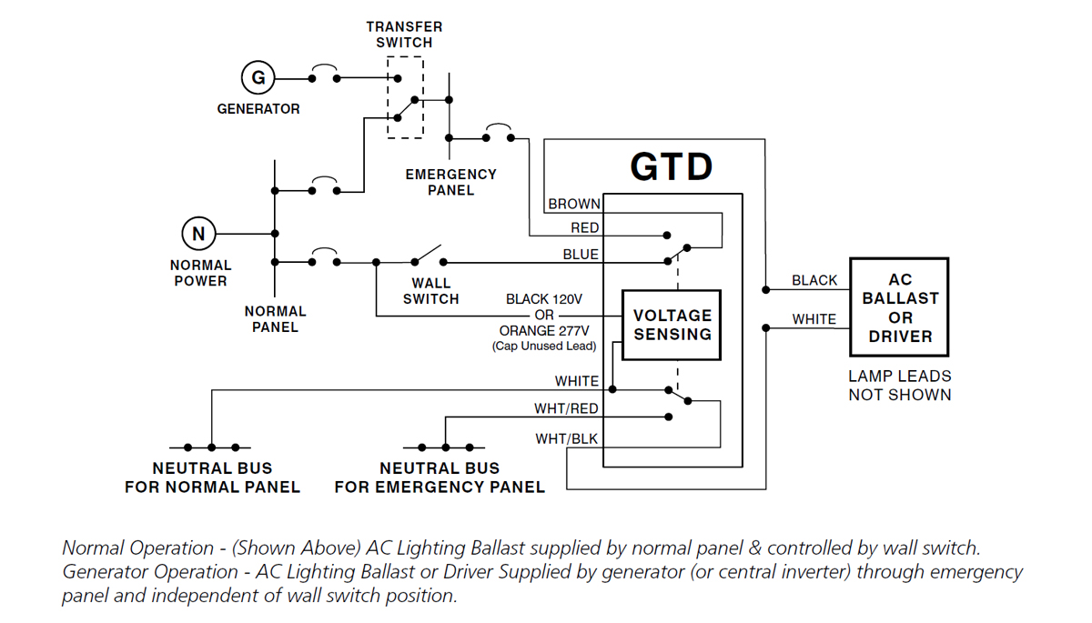
Remove gtd20a lid and install necessary conduit and wiring not supplied to the gtd20a. Page 1 circuit wiring is available.

Read Or Download Pool Pump Wiring Diagram For 230 Volt
Bodine gtd20a wiring diagram. The gtd20a is suitable for use in indoor and damp locations. Connection diagram for 230460vac 9 wire reversible 3 phase gearmotors and motors 07410012. Operation the gtd20a senses the loss of normal power and switches the lighting load connecting it to. The gtd20a includes three dry form c contacts which allows the user a wide variety of wiring options. The gtd20a is suitable for use in indoor and damp locations. The gtd20a includes three dry form c contacts which allows the user a wide variety of wiring options.
Operation the gtd20a senses the loss of normal power and switches the lighting load connecting it to a. See table 1 3. Check to see if brown connector is properly used. For generator or central inverter supplied lighting. Refer to the illustrations on the following pages for proper wiring connections and choose the correct illustration for your application. For additional applications and information contact the factory.
The gtd20a includes three dry form c contacts which allows the user a wide variety of wiring options. Summary of contents for bodine gtd20a. A separate connection to. Ul listed for us and canada under ul 924 ul listed for the us under ul 1008. For additional applications and information contact the factory. An unswitched normal ac power source 120 through 277 vac 5060 hz and a direct separate connection to a.
Check to make sure lamps are good operational and specified for self testing emergency ballast and in place. Flashing 4 times every 10 seconds battery discharge is too low during scheduled self test 1. To verify that this is the correct wiring diagram for your bodine product please check for the connection diagram reference number in the specifications table on the applicable itemmodel page. When using class 2 power limited circuits for example 0 10v dimming connections. Check that fixture wiring is in accordance with proper wiring diagram. Click download pdf to view this wiring diagram.
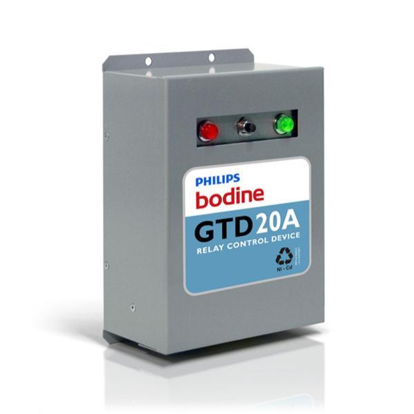
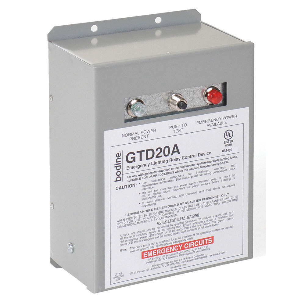
The gtd20a does not affect normal fixture operation and comes fully assembled for immediate installation. For additional applications and information contact the factory. An unswitched source of normal power is required. Use the proper wiring diagram in the appropriate section of these instructions. In addition to available wiring the device requires a direct unswitched connection to a normal power circuit and depending on the application an unswitched connection to a generator supplied or central inverter system supplied standby. The gtd20a is suitable for use in indoor and damp locations.
